Salt chlorine generator

a technology of salt chlorine generator and electrolytic cell, which is applied in the field of halogen producing electrolytic cell, can solve the problems of difficulty in removal of electrodes plates for replacement or cleaning, high cost and large size of electrodes, and prevent access to wires, etc., and achieves the effect of eliminating the necessity, low cost, and easy installation

Active Publication Date: 2006-03-21
SMARTPOOL
View PDF26 Cites 27 Cited by
  • Summary
  • Abstract
  • Description
  • Claims
  • Application Information

AI Technical Summary

Benefits of technology

[0009]It will be appreciated that there is a need for a low cost, easily installed electrolytic cell that produces halogen disinfectants without hiring specialized contractors and eliminates the necessity of extensive monitoring equipment. Ideally the design should provide for the constant disbursement of disinfectant into the body of water which maximizes performance; at a much lower cost to consumers due to smaller electrodes and is capable of self installation; ease of maintenance and a unitized fitting that easily replaces all existing water circulation fittings for which it is designated.

Problems solved by technology

A common difficulty of the first type is the high cost and large size of the electrodes, which require extensive electronic monitoring equipment to insure safety and proper disinfection.
The difficulty with this embodiment is the necessity to insert wiring through the vessel wall and route wires through existing pool piping which precludes access to the wires for service or replacement and the difficulty in removal of electrodes plates for replacement or cleaning.
In addition to the drawbacks outlined above, the existing systems require a high initial purchase price due to the large size of the cell and the electronic monitoring sensors required for operation.
Further, the costs associated with the hiring of specialized contractors to complete the installation and to service the unit are substantial.

Method used


Image

  • Salt chlorine generator
  • Salt chlorine generator
  • Salt chlorine generator

Examples


Embodiment Construction

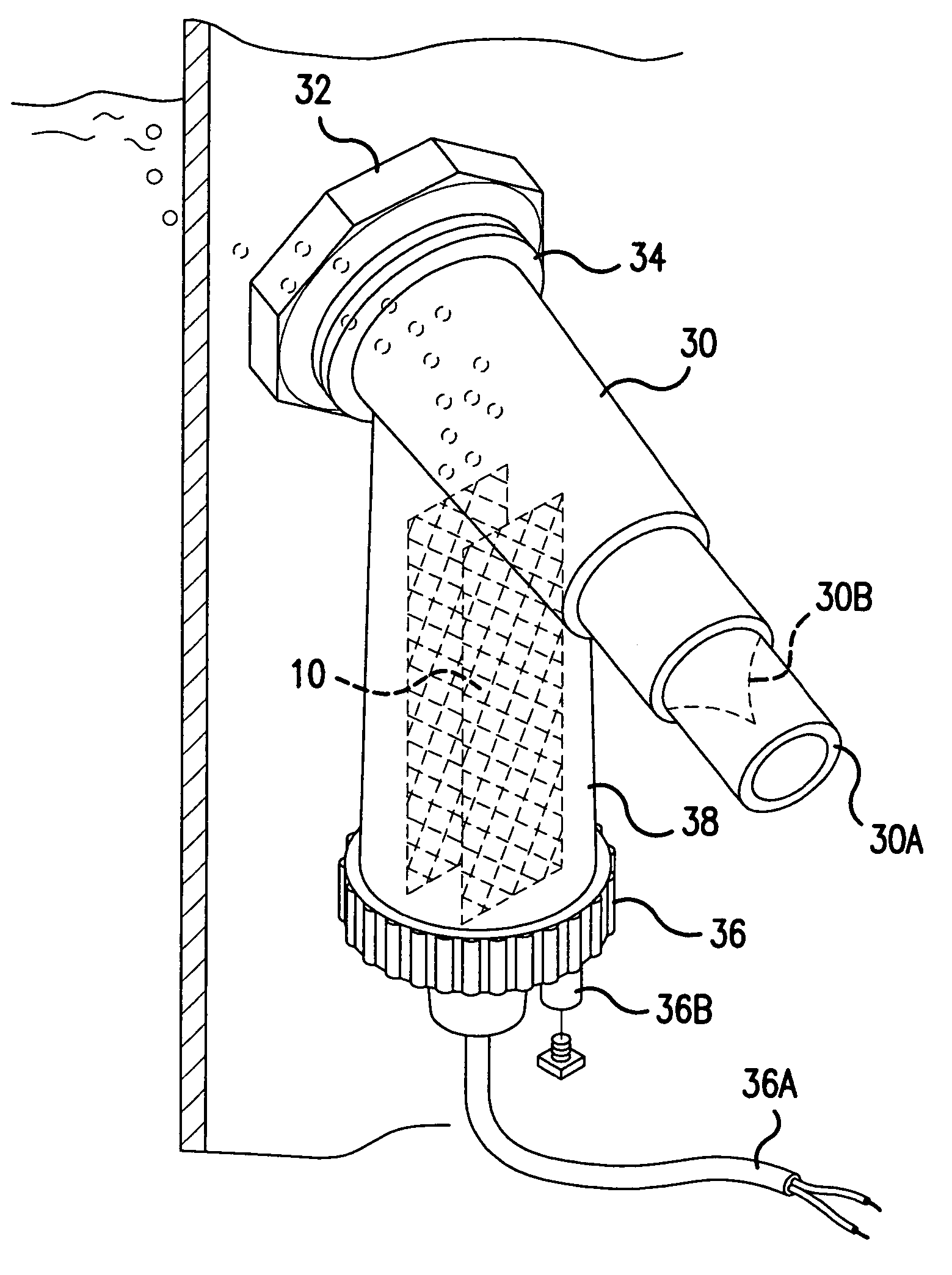
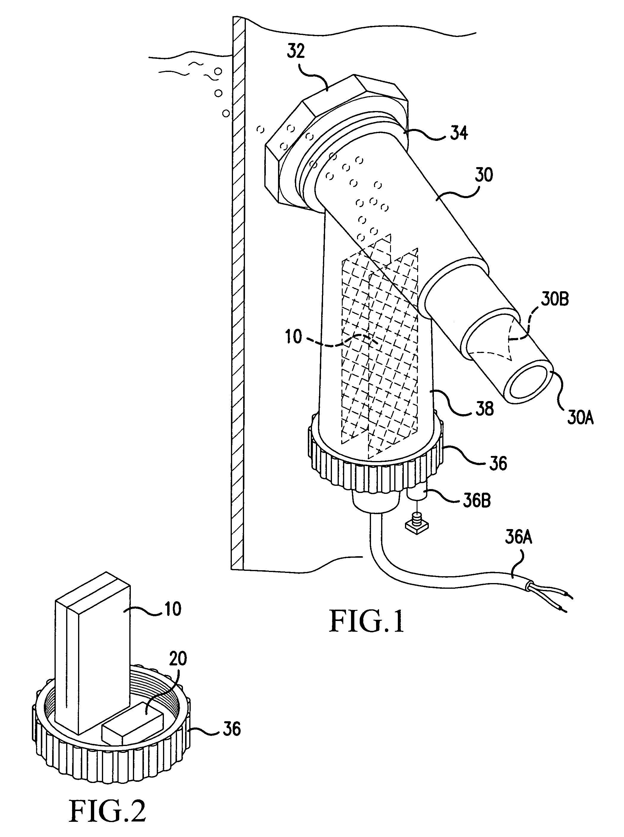
[0018]As illustrated in FIGS. 1 and 2, the present invention resides in a combination of a halogen producing electrolytic cell 10, a circulation pump 20, a directional check valve 30B and a liquid circulation fitting 30 formed as a unitary structure. It is to be understood that the components may be arranged as individual components.

[0019]In one preferred embodiment, the liquid circulation fitting 30 is a return water inlet fitting formed integrally as a unitary structure with a halogen producing electrolytic cell 10 to be installed in a single opening 32 in the wall of a pool, spa, hot tub or other vessel. The halogen producing electrolytic cell 10 also contains an integrated, dedicated circulation pump 20 inside the unitary structure.

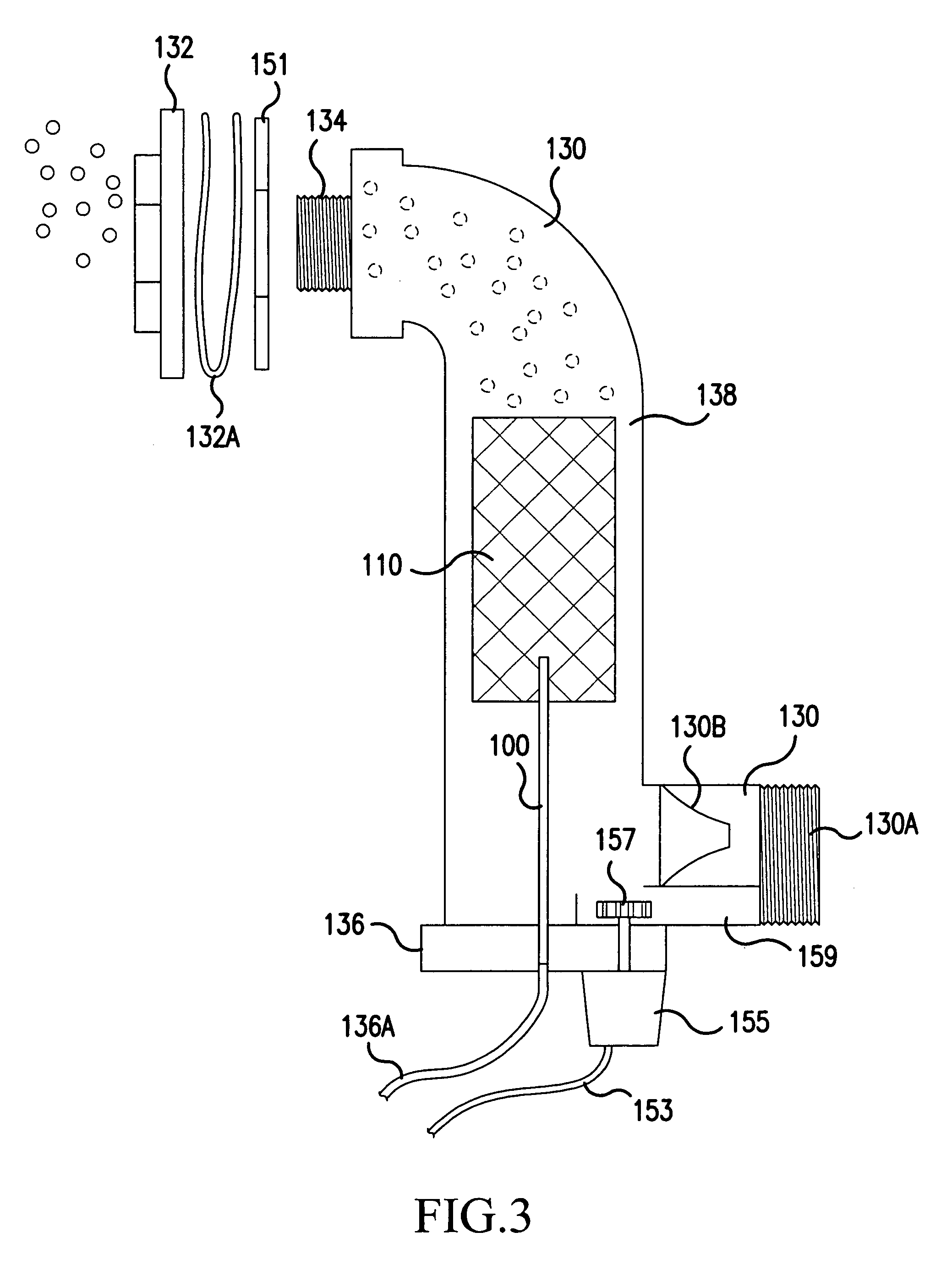
[0020]A one-way check valve 30B is provided to permit a full flow of water through the structure only when the pool pump is in operation. When the pool pump is not operating, fresh water is drawn by the circulating pump within the structure from a spe...


PUM

PropertyMeasurementUnit
angleaaaaaaaaaa
sizesaaaaaaaaaa
thicknessesaaaaaaaaaa

Abstract

An electrolytic cell combined into a unitary structure with a liquid circulation fitting, which purifies water by electrode plates inside the cell when an aqueous solution is present. The unitary structure replaces the existing water return fitting. This integrated structure is well suited for use in pools, tubs, spas, fountains or similar large liquid containers. The production of halogen inside the structure is not required to coincide with the cycle of the existing pool filtration system. Rather, the electrodes receive a continuous supply of low level power and the halogen produced inside the structure is disbursed back into the body of water through the fitting using an integrated, dedicated circulation pump, special channels in the surface and a check valve to insure one directional flow from the pool pump and natural convection. Using fresh water drawn from the vessel, halogen is then disbursed back into the vessel with the water at a location different from where the fresh water was drawn. The level of halogen production may be regulated using a timing mechanism and/or sensors in the circuitry.

Description

[0001]This Non-provisional application claims priority under 35 U.S.C. § 119(e) on U.S. Provisional Application No(s). 60 / 488,445 filed on Jul. 21, 2003, the entire contents of which are hereby incorporated by reference.BACKGROUND OF THE INVENTION[0002]1. Field of the Invention[0003]The present invention relates to a combination of a halogen producing electrolytic cell, a circulation pump, a directional flow check valve and a liquid circulation fitting formed as a unitary structure or as individual components.[0004]2. Description of Background Art[0005]Disinfection of pools, spas hot tubs, fountains or other large vessels of recirculated water is accomplished by the addition of halogen type disinfectants or by halogen generated within a cell inserted into the plumbing of the filtration loop.[0006]These halogen generation systems generally require 1) cutting or adding the generation cell to the filtration pipe loop or 2) attaching the cell to existing fittings within the body of wate...

Claims


Application Information

Patent Timeline
Patent Type & Authority Patents(United States)
IPC IPC(8): C02F1/461C01B7/03E04H4/12B01D17/06B01D21/30B01D24/00B01D25/00B01D27/00B01D29/00C01B17/00C02FC02F1/40C02F1/467C02F1/48C02F11/00C25B1/26E04H3/16
CPCC02F1/4674C02F2103/42C02F2301/046C02F2201/4611C02F2201/4615C02F2201/002
Inventor HOLSTEIN, RICHARDHUI, JOSEPH
Owner SMARTPOOL
Why Eureka
Try Eureka