

Full-automatic solder strip drying machine
A kind of drying machine, fully automatic technology, applied in the direction of drying machine, drying, progressive drying machine, etc., can solve the problems of drying, low drying efficiency, uneven drying of welding strips, etc., and achieve the drying time Short, long service life, the effect of improving work efficiency
- Summary
- Abstract
- Description
- Claims
- Application Information
AI Technical Summary
Problems solved by technology
Method used
Image


Examples
Embodiment Construction
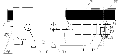
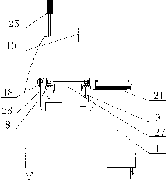
[0021] Such as Figures 1 to 7 As shown, the fully automatic welding ribbon dryer of the present invention includes a dryer box 1, a drying tank 2 is opened in the box body 1, and an inner cover 3 is covered on the drying tank 2, and the inner cover 3 is provided with a hollow The air collecting chamber 4 has a plurality of air outlets 5 at the bottom of the air collecting chamber 4, the top of the air collecting chamber 4 in the middle of the inner cover 3 communicates with the exhaust pipe 6, and the inner walls on both sides of the drying tank 2 are uniformly fixed with multiple rows of short-wave infrared rays The lamp tube 7 and the bottom of the inner cover air collecting chamber 4 are evenly fixed with multiple rows of infrared short-wave lamp tubes 7 . The inner wall on both sides of the drying tank 2 in the length direction is also fixed with a conveying chain 8, the conveying chain 8 is provided with a plurality of belt hooks 9, and the top of the box body 1 is provi...
PUM
 Abstract
Description
Claims
Application Information