Method for controlling a cutting extraction machine

A mining machine, cutting-type technology, applied in the field of controlling cutting-type mining machines, can solve problems such as hindering thermal radiation measurement

Active Publication Date: 2010-09-08
EICKHOFF BERGBAUTECHN
View PDF1 Cites 15 Cited by
  • Summary
  • Abstract
  • Description
  • Claims
  • Application Information

AI Technical Summary

Problems solved by technology

Dust and water mist also seriously hamper the measurement

Method used


Image

  • Method for controlling a cutting extraction machine
  • Method for controlling a cutting extraction machine
  • Method for controlling a cutting extraction machine

Examples


Embodiment Construction

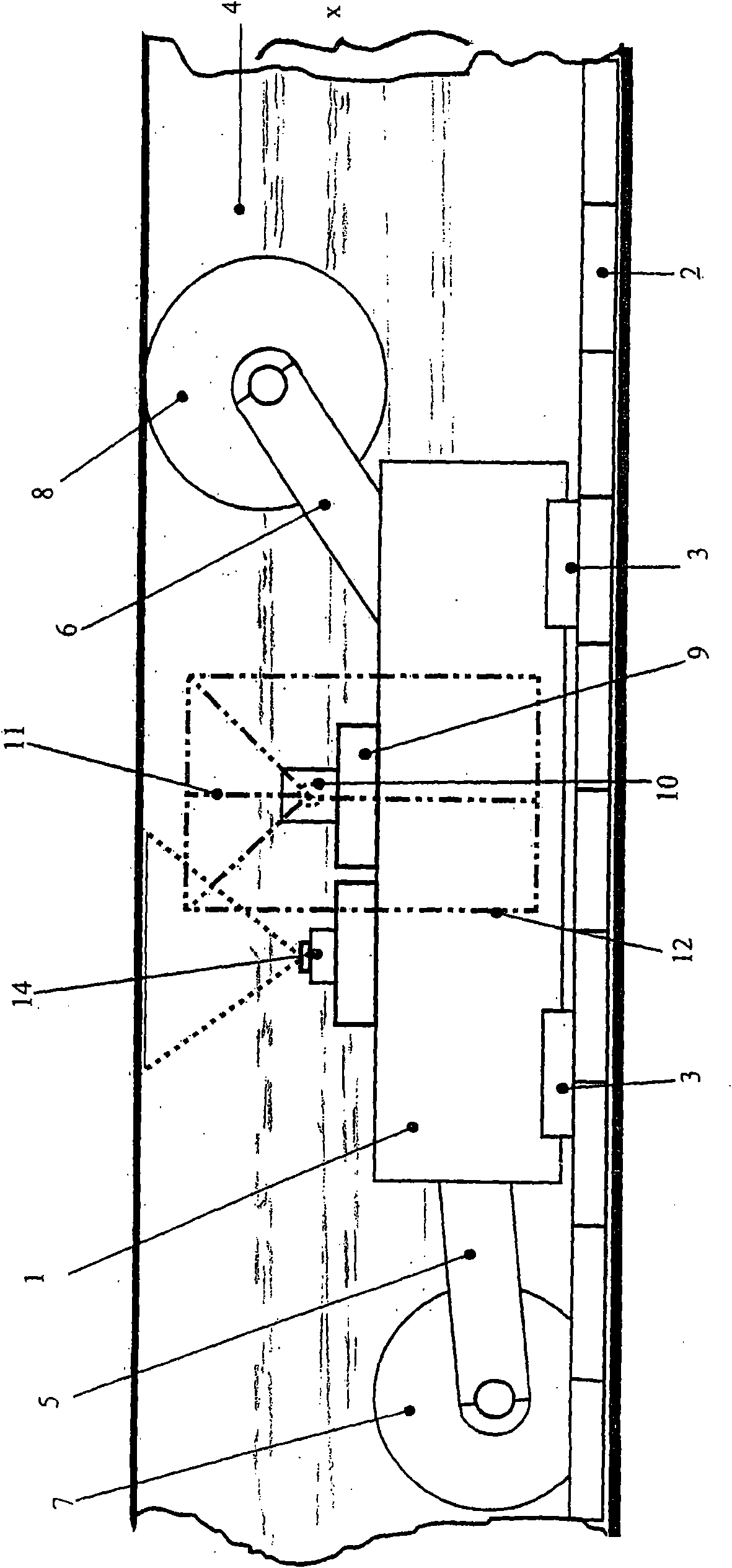
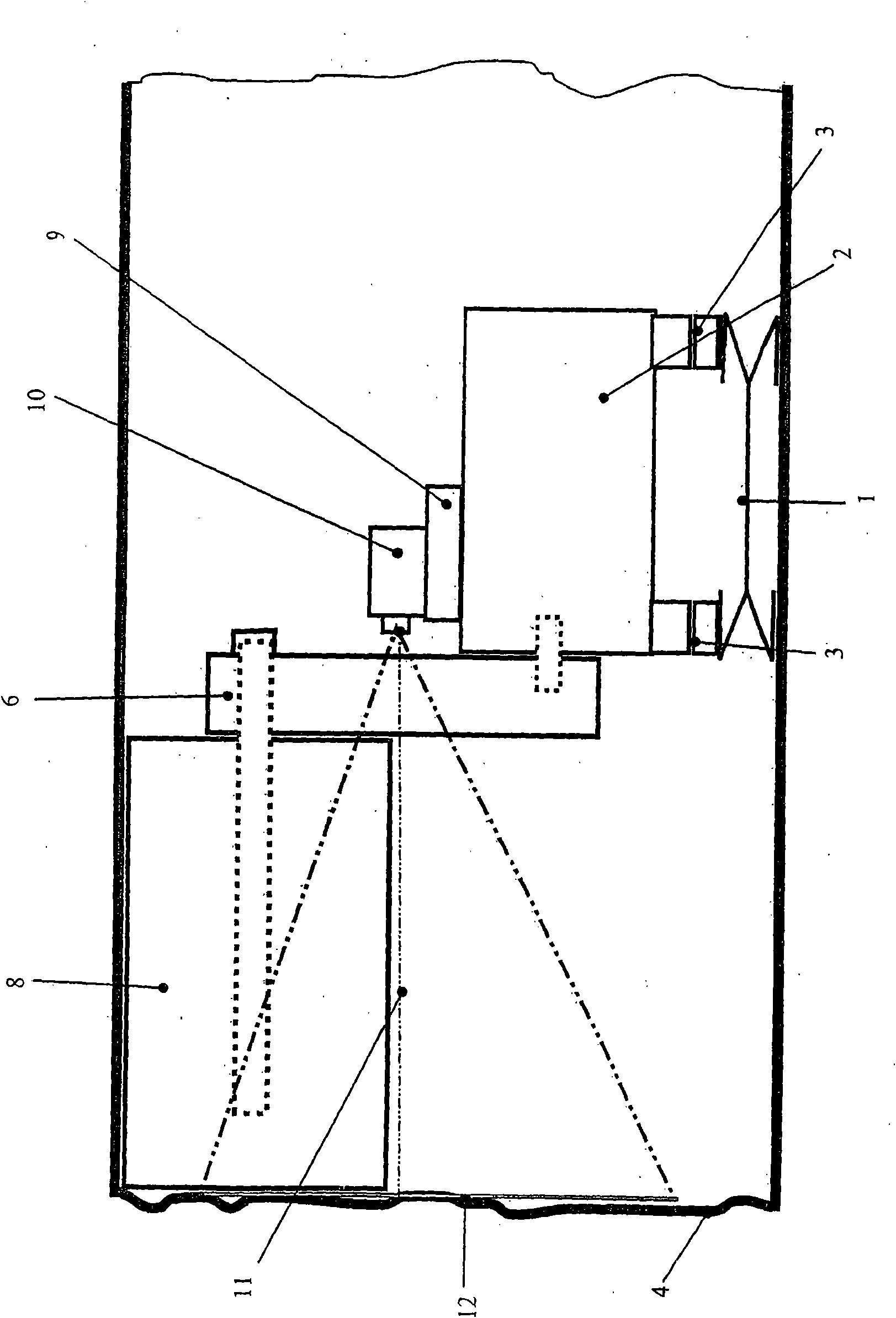
[0023] In the drawings, the body of the cutting mining machine, here the drum shearer, is marked with the reference number 1 . This body is provided with roller type slide shoes 2 below, and these roller type slide shoes can move along the working front wall 4 of the working face on the working face conveyor 3. The face conveyor 3 is thus at the same time a track for the cutting miner.

[0024] At the front and rear ends in the direction of travel, pivoting arms 5 and 6 are supported on the body 1, and these pivot arms 5 and 6 carry cutting drums 7 and 8, respectively, which are equipped with cutting drums on the circumference. tool.

[0025] Approximately in the middle of the body 1 there is a camera support 9 on which is mounted an infrared camera 10 whose optical axis 11 extends perpendicularly to the working front wall 4 .

[0026] Infrared camera 10 collects a rectangular measurement field 12 on the front wall of the work, and the measurement field is figure 1 Shown wi...


PUM


Abstract

The invention relates to a method for controlling a cutting extraction machine that can be displaced along a coal face in longwall mining, wherein the radiated heat of the working face (4) newly exposed by the extraction machine is observed by means of an infrared camera (10), and control data for the subsequent extraction travel is generated using said observation. In order to make said method error-free and better suited for practical application, the invention proposes that the observation of the radiated heat is done perpendicular to the working face (4) at a minimum distance from the cutting tools of the extraction machine, and that a guiding layer package (X) having a characteristic sequence of boundaries between layers of differing heat conductivity is determined, and that the course of said guide layer package (X) relative to the boundaries of the face is determined at the end of each extraction travel using the heat images, and that the control data for the next extraction travel of the extraction machine is generated using said course of the guide layer package.

Description

technical field [0001] The invention relates to a method for controlling a cutting-type mining machine, in particular for coal mining, which can be moved within the working face along the mining face in longwall face mining, in which method by means of At least one infrared camera associated with the mining machine observes the thermal radiation corresponding to the working face wall newly exposed by the mining machine, and generates control data for a subsequent mining work stroke of the mining machine on the basis of this observation. Background technique [0002] Such a method is known from WO 2006 / 119534 A1. This known method starts from the phenomenon known to every miner or geologist, that is, in layered deposits, such as in coal deposits, generally thin rock layers are embedded in the material to be mined, parallel to the Top and bottom floors extended. In this regard, the above-described method derives from the idea that when using a cutting-type mining machine in ...

Claims


Application Information

Patent Timeline
IPC IPC(8): E21C35/08
CPCE21C41/18E21C35/08E21C27/34
Inventor B·哈克伯格尔F·马维鲁迪斯R·温克尔K·宁豪斯
Owner EICKHOFF BERGBAUTECHN
Why Eureka
Try Eureka