Multi-stage pump rotor for turbo-molecular pump

A technology of turbomolecular pump and multi-stage pump, which is applied to components, pumps, and pump components of pumping devices for elastic fluids, can solve problems such as the weakening of the inherent design of the rotor, and reduce the risk of bursting and damage. force and effect

Active Publication Date: 2010-09-08
LEYBOLD HERAEUS GMBH & CO KG
View PDF0 Cites 4 Cited by
  • Summary
  • Abstract
  • Description
  • Claims
  • Application Information

AI Technical Summary

Problems solved by technology

The described bell-shaped configuration of the pump rotor will result in a weakening of the inherent design of the rotor
In the pump rotors of turbomolecular pumps, which are usually formed as a one-piece unit, this inherent design weakness can only be compensated by the use of extremely expensive high-strength aluminum alloys

Method used


Image

  • Multi-stage pump rotor for turbo-molecular pump
  • Multi-stage pump rotor for turbo-molecular pump
  • Multi-stage pump rotor for turbo-molecular pump

Examples


Embodiment Construction

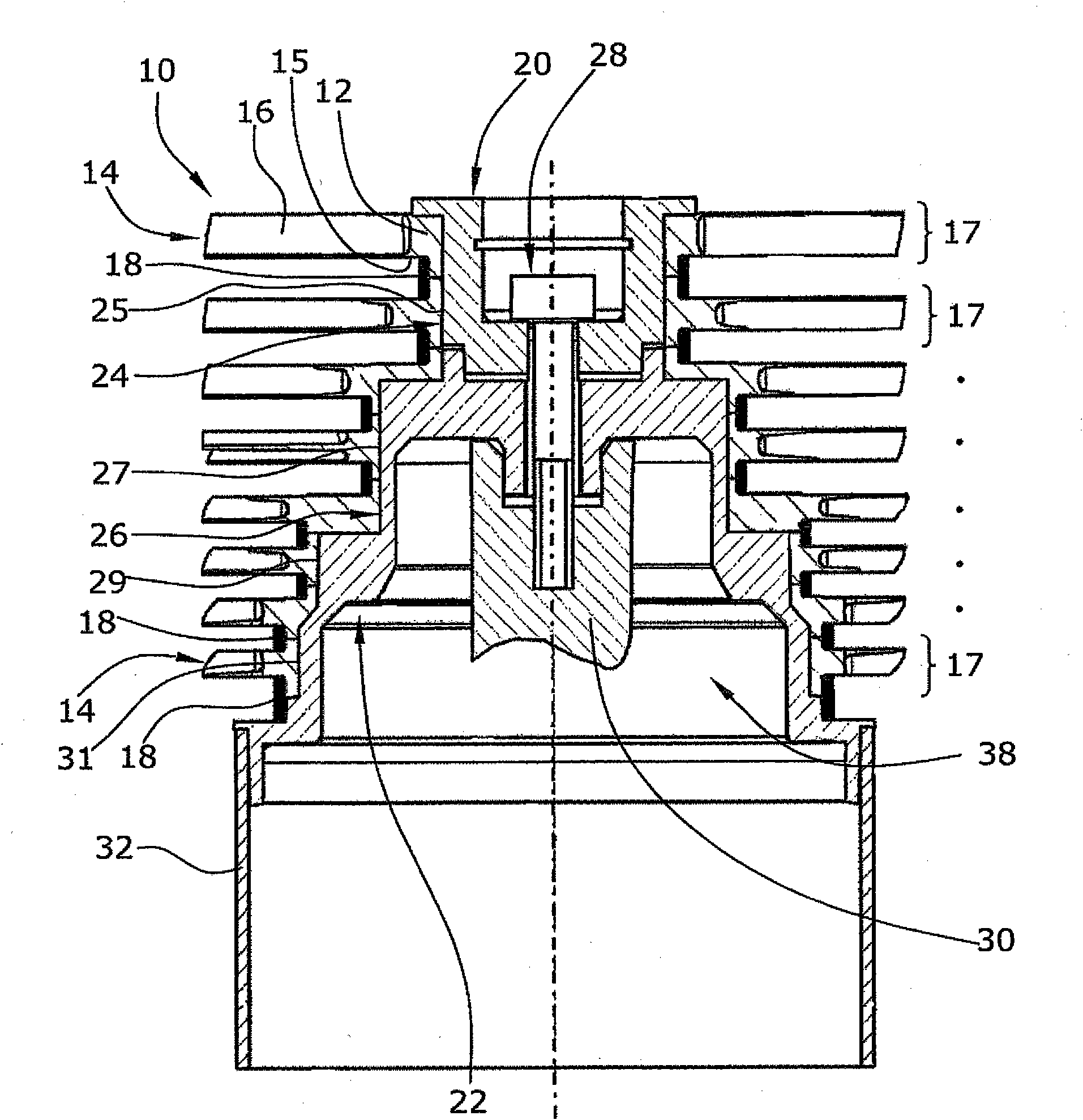
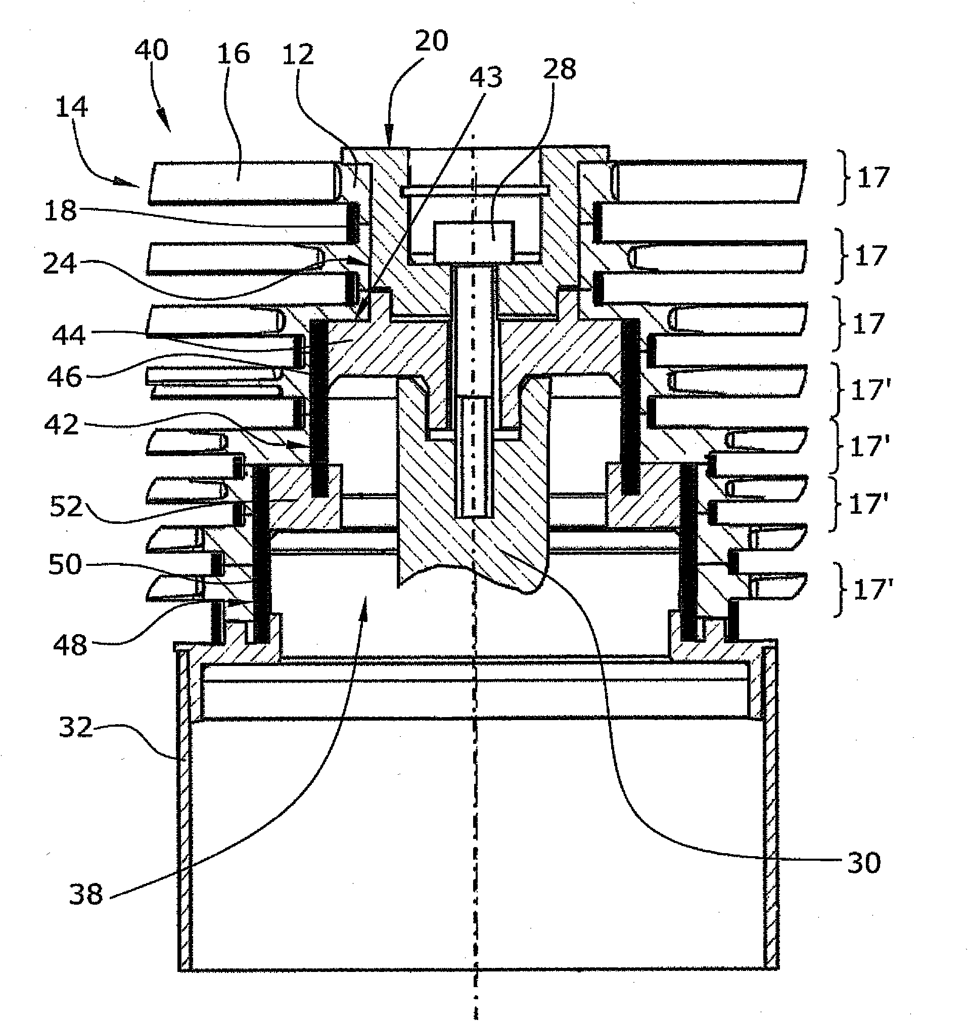
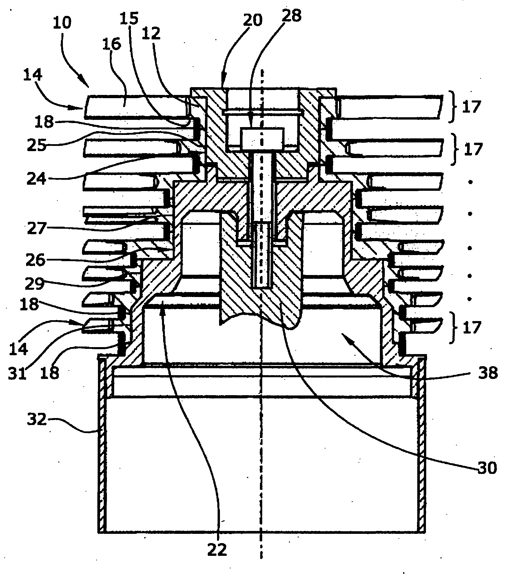
[0024] exist figure 1 and 2 In , multistage pump rotors 10, 40 for turbomolecular pumps are shown, respectively. The pump rotor 10, 40 is adapted to rotate at a nominal rotational speed of 20,000 r / min to 100,000 r / min. The two pump rotors 10 , 40 have approximately the same design, only their internal construction differs from one another.

[0025] according to figure 1 The rotor 10 is substantially formed by eight blade disk rings 17 which are axially clamped to each other by means of two clamping bodies 20 , 22 which themselves are clamped by clamping screws 28 and the shaft 30 are axially clamped to each other. Furthermore, a rotor-side Holweck cylinder 32 is provided next to the blade disk ring 17 .

[0026] The pump rotor 10 is not designed as a one-piece unit, as conventional pump rotors of the prior art are, but consists of a plurality of blade disk rings 17 . Each blade disk ring 17 is formed by a closed rotor ring 12 with rotor blades 16 extending in radially o...


PUM


Abstract

The invention relates to a multi-stage pump rotor (10) for a turbo molecular pump. The pump rotor (10) has at least two separate blade disk rings (17), each having a rotor ring (12) and at least one blade disk (14). A cylindrical reinforcement pipe (18), which surrounds the rotor rings (12) of the blade disk rings (17) on the outside without clearance, is provided between the blade disks (14) of adjacent blade disk rings (17). The reinforcement pipe (18) absorbs a large part of the tangential forces occurring during operation such that the pump rotor (10) has improved stability at high rotor speeds.

Description

technical field [0001] The invention relates to a multistage pump rotor of a turbomolecular pump. Background technique [0002] Existing turbomolecular pumps operate at a rotational speed of tens of thousands of r / min (revolutions per minute). In relatively large turbomolecular pumps, the kinetic energy of the pump rotor operating at this nominal rotational speed is in the range of that of a small car traveling at 50 km / h (kilometers per hour) to 70 km / h. When the rotor bursts, this high kinetic energy will likely result in serious damage and injury which can only be kept under control with a considerable investment in the mechanical protection of the rotor. [0003] Particularly with magnetically supported cantilevered pump rotors for turbomolecular pumps, this can be very problematic due to their extremely prone to bursting properties. In magnetically supported pump rotors of the cantilever type, the designer will aim to arrange at least one radial bearing and the drive ...

Claims


Application Information

Patent Timeline
Patent Type & Authority Applications(China)
IPC IPC(8): F04D19/04F04D29/64F04D29/32
CPCF04D29/644F04D29/321F04D19/042F04D19/048
Inventor 海因里希·恩伦德尔
Owner LEYBOLD HERAEUS GMBH & CO KG
Why Eureka
Try Eureka