Ring die pelleter

A granulator and ring die technology, applied in presses, manufacturing tools, presses for material forming, etc., can solve problems such as uneven impact force, unequal gaps, and easy damage to main shaft bearings, and reduce cantilever loads. The effect of reducing power consumption and uniform force

Active Publication Date: 2010-09-15
扬州华美知识产权事务有限公司
View PDF9 Cites 6 Cited by
  • Summary
  • Abstract
  • Description
  • Claims
  • Application Information

AI Technical Summary

Problems solved by technology

The pressure roller assembly and the main shaft are rigidly connected, and the ring die and the rotor are also rigidly connected, that is, the two sets of rigid parts are in a single cantilever state. When the cantilever distance is long and the load is large, it is easy to cause ring molding The pellet machine vibrates, the ring die connecting bolts are easy to loosen and break, and the main shaft bearing between the main shaft and the rotor is also easy to be damaged
[0006] 2. In the current structure of the pressure roller assembly, the eccentricity of the three pressure rollers is adjusted irregularly, resulting in unequal gaps between the outer circumference of the three pressure rollers and the inner circumference of the ring die
On the one hand, the centers of the circumscribed circles of the three pressing rollers are not concentric with the main shaft, and poor dynamic balance will cause vibration; The radial force suffered by each pressing zone is not equal, and the ring die is also subjected to uneven impact force, and the two sets of rigid bodies cannot adjust the above uneven impact force under the constraints of the two main shaft bearings, which also causes ring molding. Granulator vibrates, which leads to loosening and damage of parts

Method used


Image

  • Ring die pelleter
  • Ring die pelleter
  • Ring die pelleter

Examples


Embodiment Construction

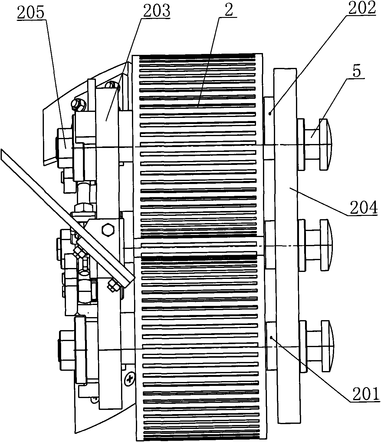
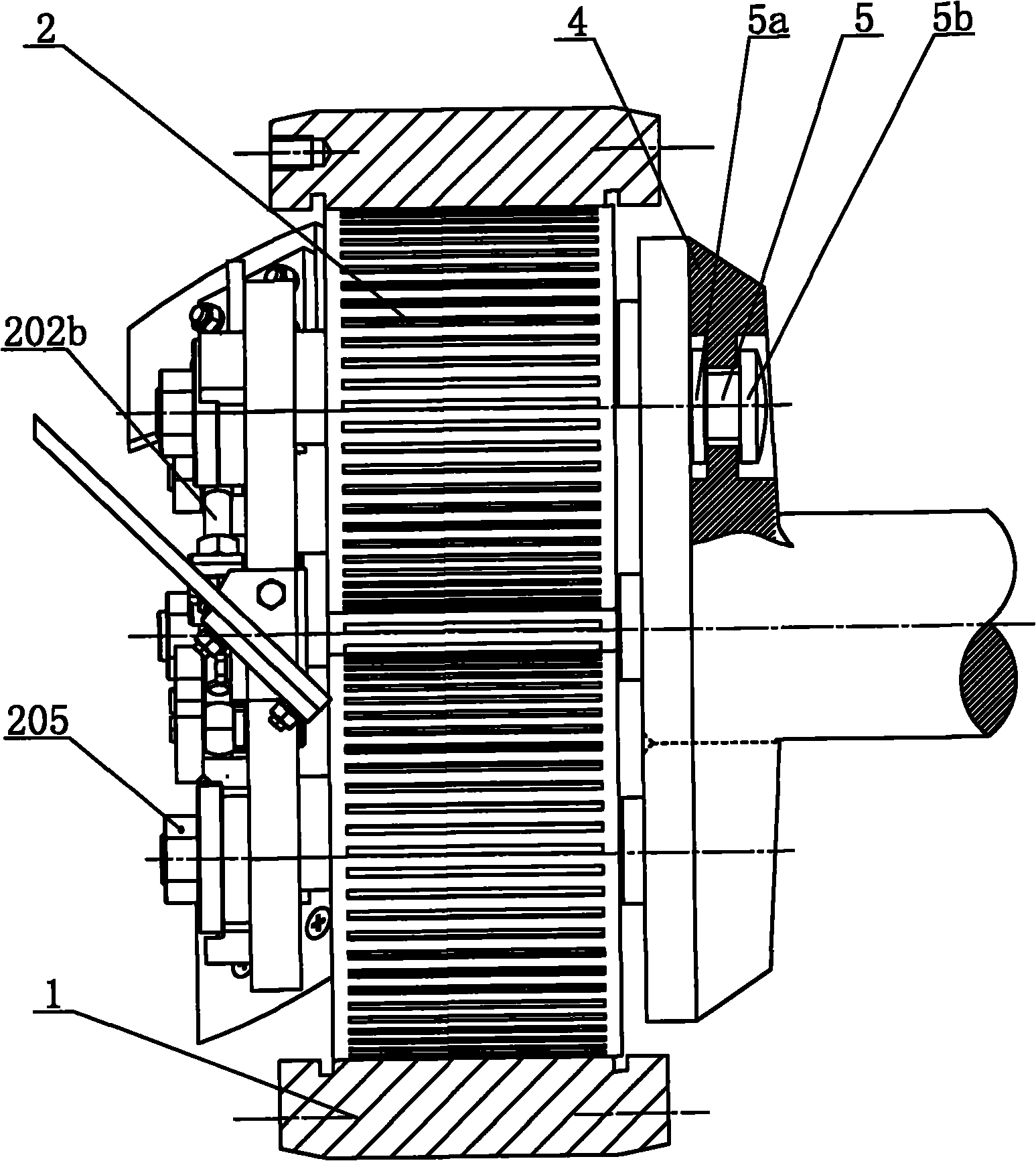
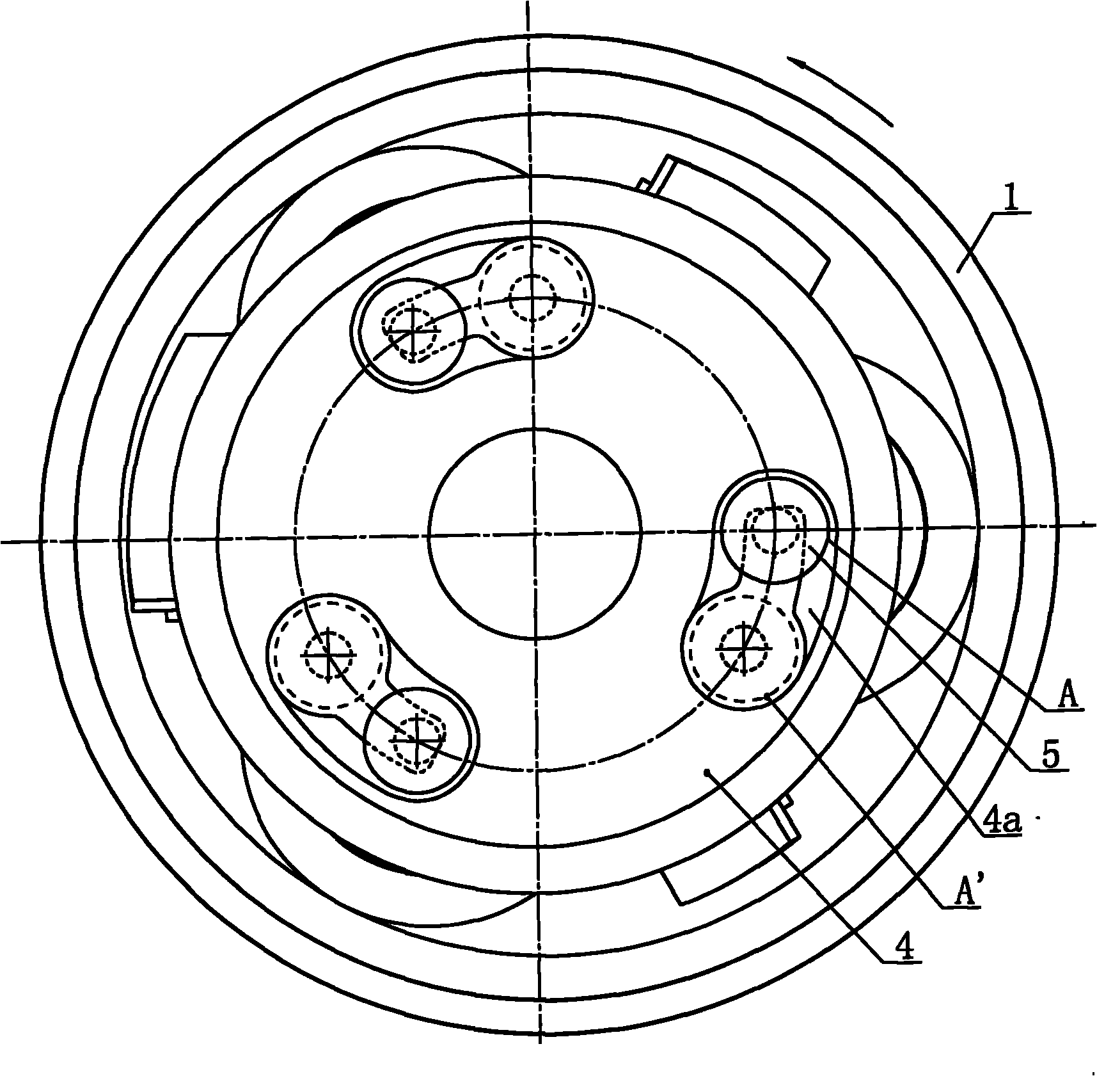
[0026] Such as figure 1 , figure 2 and Figure 6 As shown, the ring die granulator of the present invention includes a ring die 1, a pressing roller assembly 2 and a main shaft 3, the pressing roller assembly 2 is located in the ring die 1 as a whole, and the pressing roller assembly 2 includes two pressing roller support shafts 201, a Pressure roller eccentric shaft 202, front plate 203 and rear plate 204, three pressure rollers are distributed in a triangle, the two ends of pressure roller support shaft 201 and pressure roller eccentric shaft 202 are respectively supported on front plate 203 and rear plate 204, pressure roller lock The tightening nut 205 fixes the three pressure rollers from the outside of the front plate 203, one of the three pressure roller support shafts is the pressure roller eccentric shaft 202, and an eccentric shaft adjustment device connected with the pressure roller eccentric shaft 202 is provided on the outside of the front end of the front plate...


PUM


Abstract

The invention discloses a ring die pelleter belonging to the field of the feed machinery. A pressing roll assembly of the ring die pelleter is wholly arranged in a ring die; the pressing roll assembly comprises three pressing roll supporting shafts, a front plate and a rear plate; the three pressing roll supporting shafts are distributed in a triangle shape; two ends of each pressing roll supporting shaft are respectively supported on the front plate and the rear plate, and each pressing roll supporting shaft is locked by pressing roll locking nuts outside the front plate; one of the three pressing roll supporting shafts is a pressing roll eccentric shaft; connecting pins are evenly distributed on the rear end surface of the rear plate; the end of a main shaft, which is the same as that of the pressing roll assembly, is provided with connecting discs; the connecting discs are provided with pin slots which are respectively matched with the connecting pins; and the connecting pins are respectively clamped in the corresponding pin slots of the connecting discs. The main shaft of the ring die pelleter only supports a rotor assembly and restricts the pressing roll assembly from rotating along with the rotor assembly, and the rotor assembly only outputs power to the ring die, thus the load of the cantilever for the main shaft, the vibration and the damage of the bearing and other components are reduced, and less power is consumed.

Description

technical field [0001] The invention relates to a feed machine, in particular to a ring die granulator capable of extruding powdery materials into granules through three pressing rollers and a ring die. Background technique [0002] Ring die granulator includes frame, ring die, rotor, pressing roller assembly, main shaft and feeding and discharging parts. The pressure roller assembly includes three pressure roller support shafts, a front plate and a rear plate. The three pressure roller support shafts are distributed in a triangle shape. The two ends of each pressure roller support shaft are respectively supported on the front plate and the rear plate. In the mold, the outer circumference of the three pressure rollers on the three pressure roller support shafts and the inner wall of the ring die form a pressing cavity. The points of contact are in a circle whose center is concentric with the principal axis. The pressing roller assembly is respectively fixed on one end of t...

Claims


Application Information

Patent Timeline
Patent Type & Authority Applications(China)
IPC IPC(8): A23N17/00A23P1/02A23P10/25
CPCB30B11/201
Inventor 黄祁凯
Owner 扬州华美知识产权事务有限公司
Why Eureka
Try Eureka