Human body simulation manipulator for handicapped

A technology for human simulation and disabled people, applied in the field of artificial manipulators, can solve the problems of long distance, volume, fragile degree of human simulation, insufficient firmness of items, etc., and achieve the effect of holding items firmly

Inactive Publication Date: 2010-09-15
王连方
View PDF5 Cites 10 Cited by
  • Summary
  • Abstract
  • Description
  • Claims
  • Application Information

AI Technical Summary

Problems solved by technology

[0003] In order to solve the various shortcomings of existing manipulators, such as limited size and fragility of objects, insufficient firmness for holding objects, too far for human body simulation, and single-function technical problems, the present invention provides a handicapped robot. Human body simulation manipulator, the manipulator has a very high degree of human body simulation, can hold different volumes, fragile objects, can hold objects stably and firmly, and has other functions such as writing and other high human body simulation

Method used


Image

  • Human body simulation manipulator for handicapped
  • Human body simulation manipulator for handicapped
  • Human body simulation manipulator for handicapped

Examples


Embodiment 1

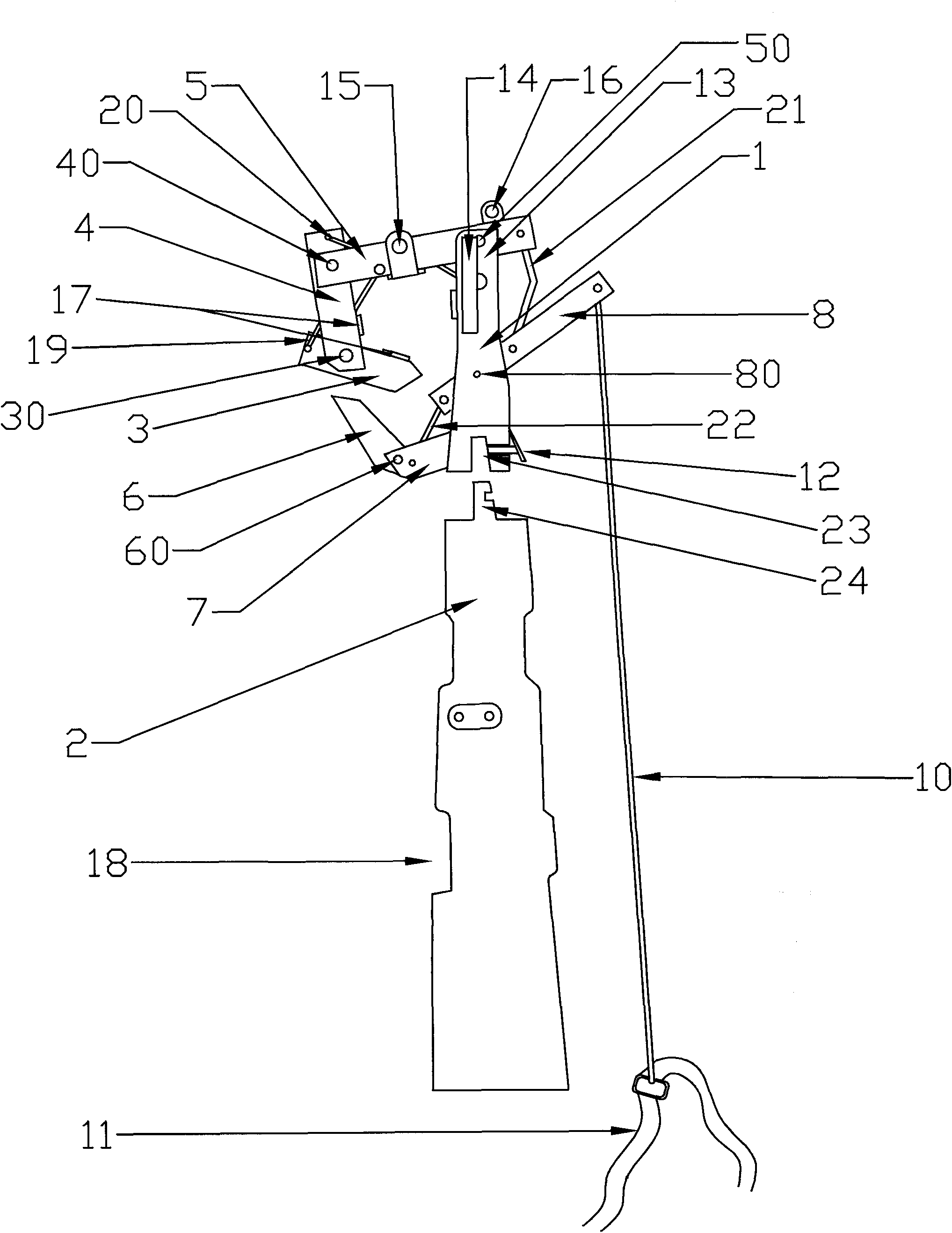
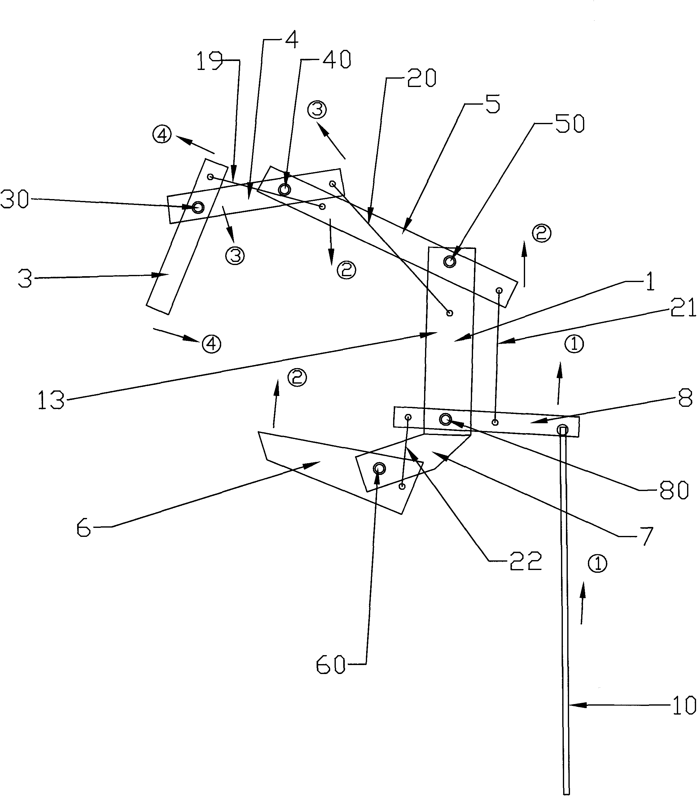
[0030] The invention is a human simulation manipulator for the disabled, as attached figure 1 , including a hand body 1 and a mechanical arm 2. The hand body and the mechanical arm can be combined and separated through a locking device 12. There are three fingers on the front side of the hand body. 5. Connected in turn, the lower part of the upper finger section and the upper end of the middle finger section are movably connected through the upper finger shaft 30, the lower part of the middle finger section is movably connected with the upper end of the lower finger section through the middle finger shaft 40, and the lower part of the lower finger section is connected with the upper end of the root of the finger through the lower finger shaft. The shaft 50 is movably connected, the rear side of the hand body is provided with a thumb 6, the lower part of the thumb and the root of the thumb 7 are movably connected through the thumb shaft 60, and the body of the hand is formed by ...

Embodiment 2

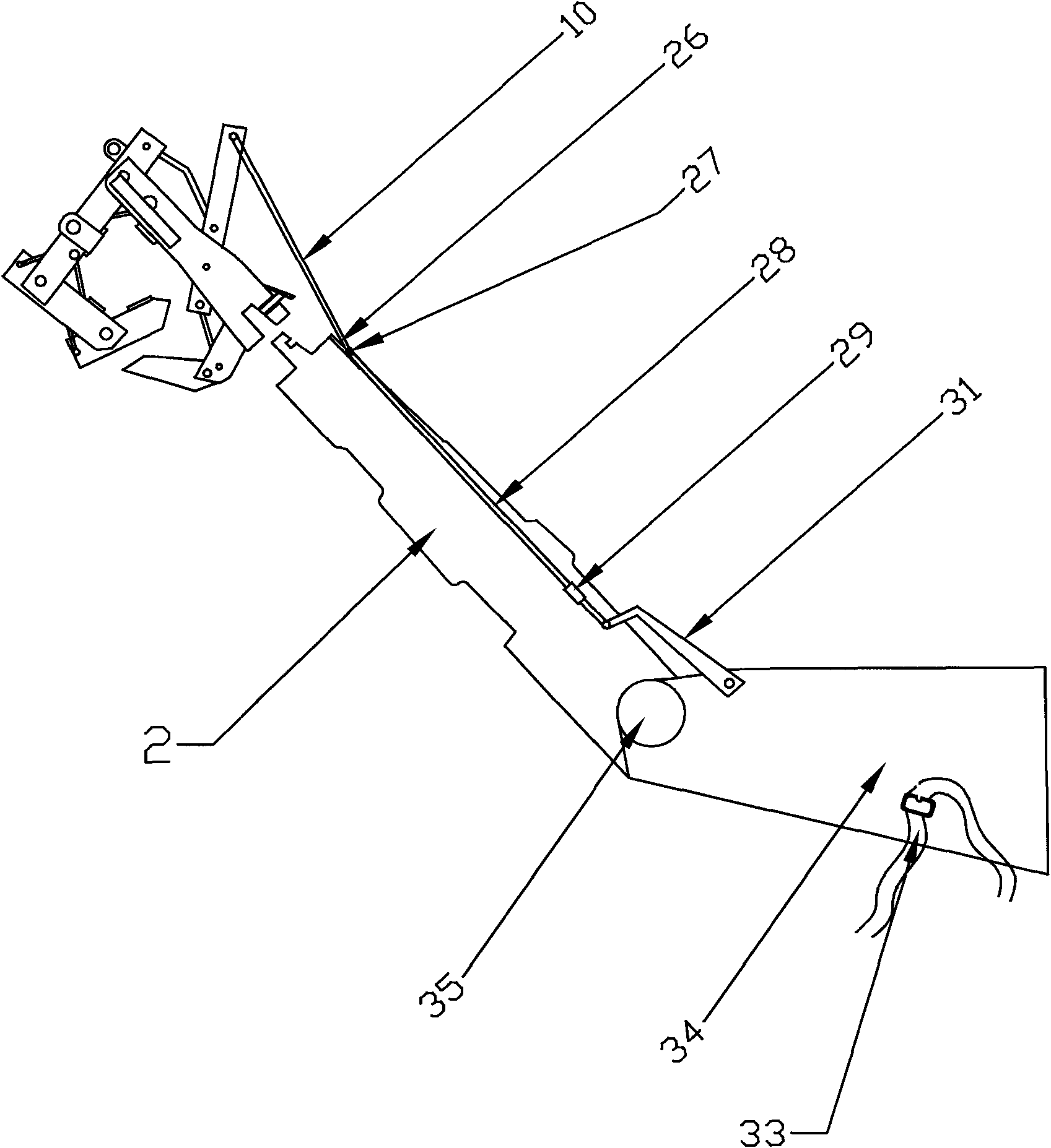
[0033] This embodiment is to add a large robot arm structure to the above embodiments, and add some excellent joints and connecting rods to make the whole robot more perfect and more convenient to use. structured as image 3 As shown, a large mechanical arm 34 is connected to the rear end of the mechanical arm, and the large mechanical arm is connected to the above-mentioned mechanical arm through a connecting joint 35. The large mechanical arm is provided with a fixing device 33, which is also bound Belt, the L-shaped connecting rod 31 that is provided with on the large mechanical arm connects the connecting rod two 28 on the mechanical arm, wherein the short rod of the L-shaped connecting rod is downward, the short rod and the long rod form a certain angle, and the length of the short rod is controlled The movement range of the connecting rod caused by the expansion and contraction of the big arm, and finally controls the movement range of the manipulator, and the second con...

Embodiment 3

[0036] This embodiment is to add a large mechanical arm, a back fixing device and a "7"-shaped connecting rod structure to the above embodiment 1. Also in this embodiment, the connecting rod and the rotating body part can also be designed according to Embodiment 2, and the structure is as follows Figure 5 As shown, a large mechanical arm 34 is connected to the rear end of the mechanical arm 2, and the large mechanical arm and the mechanical arm are rotatably connected by a connecting joint 35. The large mechanical arm is provided with a fixing device 33, which is also a binding belt. The "7"-shaped connecting rod 38 provided on the mechanical arm is connected to the back fixing device 37, wherein the short rod of the "7"-shaped connecting rod is universally connected with the mechanical arm, and the long rod of the "7"-shaped connecting rod is connected to the back fixing device. It is also universally connected to ensure the free movement of the big arm and the shoulder join...


PUM


Abstract

The invention relates to a simulation manipulator with a pure mechanical structure. The simulation manipulator is provided with multi-joint fingers. Transmission ligaments and transmission bodies receive the bending forces of arms to drive hand bodies to clench and stretch, and the magnitude of the holding force can be randomly controlled. The manipulator can very stably and firmly hold articles, can take articles with different volumes, can also hold articles with high frangibility degree stably; and meanwhile, the manipulator has human body simulation functions of writing, cooking, taking food with forks and spoons and the like, which brings great convenience for the life of the handicapped.

Description

technical field [0001] The invention relates to a simulated manipulator with a purely mechanical structure, in particular to a simulated manipulator with arms for disabled people. Background technique [0002] At present, there are two types of simulated manipulators for the disabled, with arms and without arms. Armless manipulators need to rely on muscles such as feet and chest to operate and complete simple life actions. For manipulators with arms, most of them use two-finger or multi-finger clamping to complete the actions of fetching and holding objects. Such as the patent No. CN200720071414.9 applied for the myoelectric hand mechanical hand structure and accessories, including the composition of the index finger and middle finger, thumb, hand frame plate, connecting rod, index finger-thumb shaft assembly, etc., this design is only a single A single-axis rotation is used to complete the clamping and releasing between the index finger and the thumb. Although this method ...

Claims


Application Information

Patent Timeline
Patent Type & Authority Applications(China)
IPC IPC(8): A61F2/54
Inventor 王连方
Owner 王连方
Why Eureka
Try Eureka