Filter device for a textile machine for the production of cross-wound spools

A technology of cross-winding bobbins and filter devices, which is applied in textile and papermaking, dispersed particle filtration, dispersed particle separation, etc., can solve the problems of complex manufacturing, achieve the effect of small wind loss and optimized air passage holes

Inactive Publication Date: 2010-09-15
OERLIKON TEXTILE GMBH & CO KG
View PDF3 Cites 3 Cited by
  • Summary
  • Abstract
  • Description
  • Claims
  • Application Information

AI Technical Summary

Problems solved by technology

Such a vane mechanism has indeed only a relatively small air-acting surface in the open state, but is complex and correspondingly expensive to manufacture.

Method used


Image

  • Filter device for a textile machine for the production of cross-wound spools
  • Filter device for a textile machine for the production of cross-wound spools
  • Filter device for a textile machine for the production of cross-wound spools

Examples


Embodiment Construction

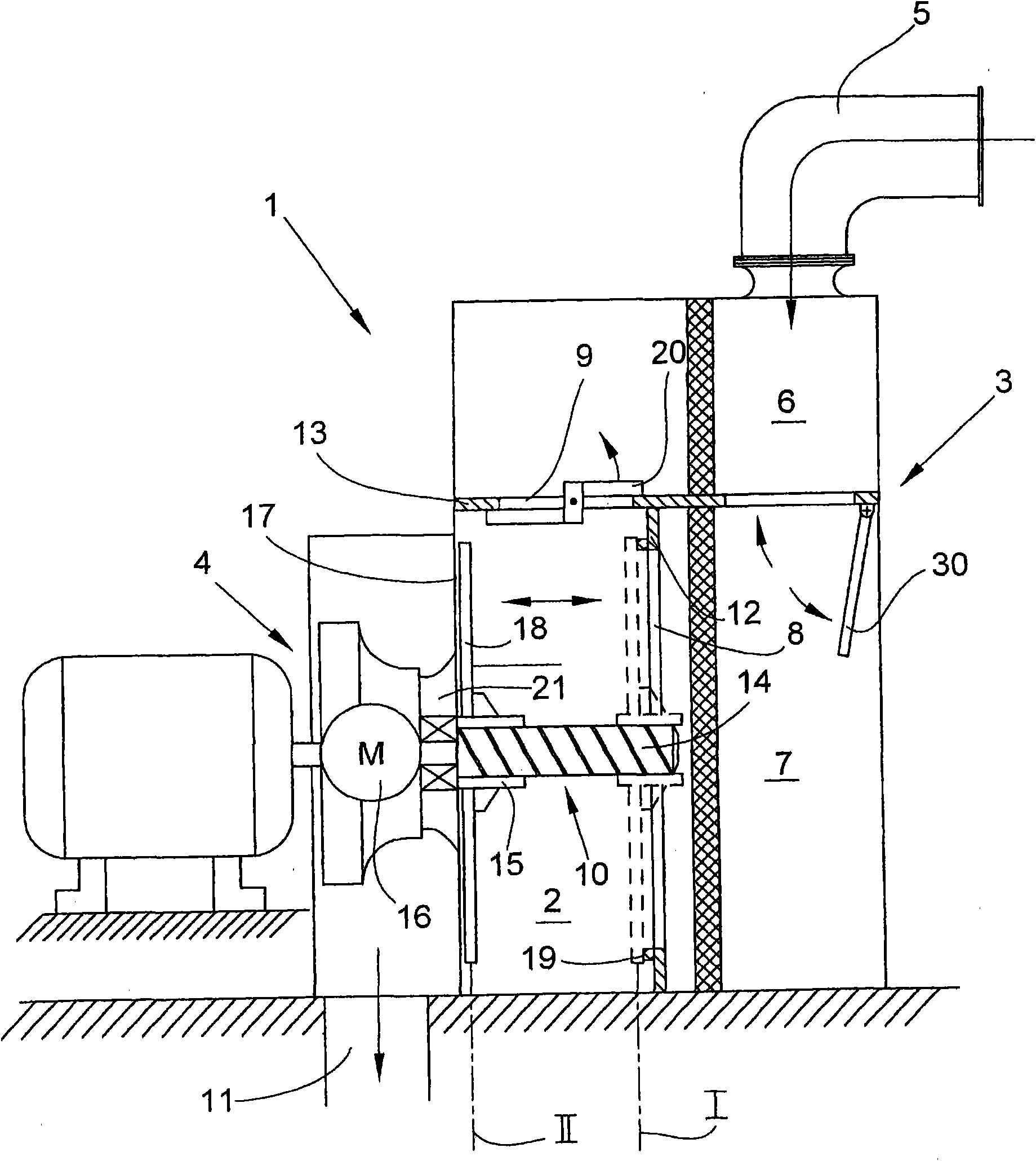
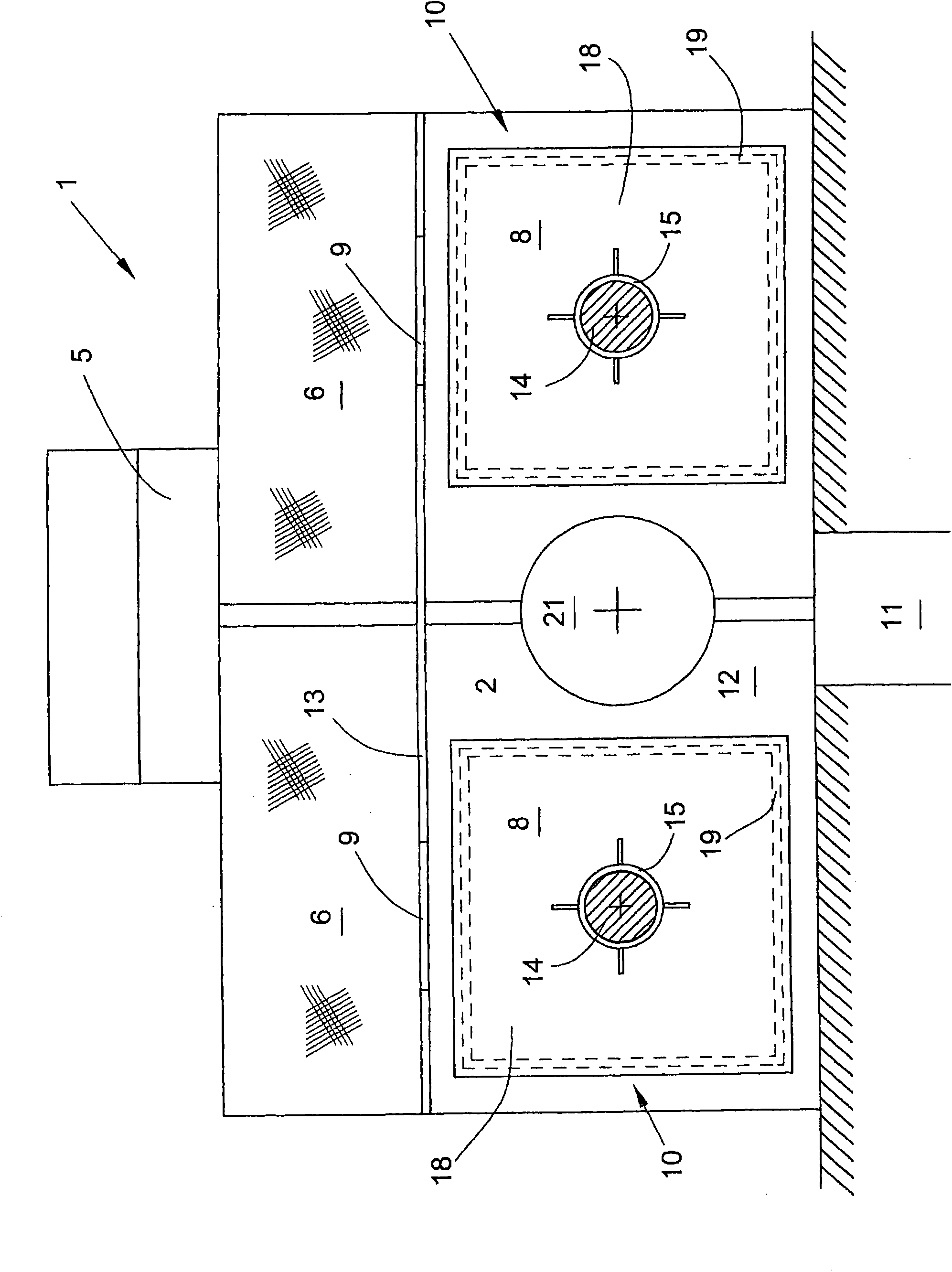
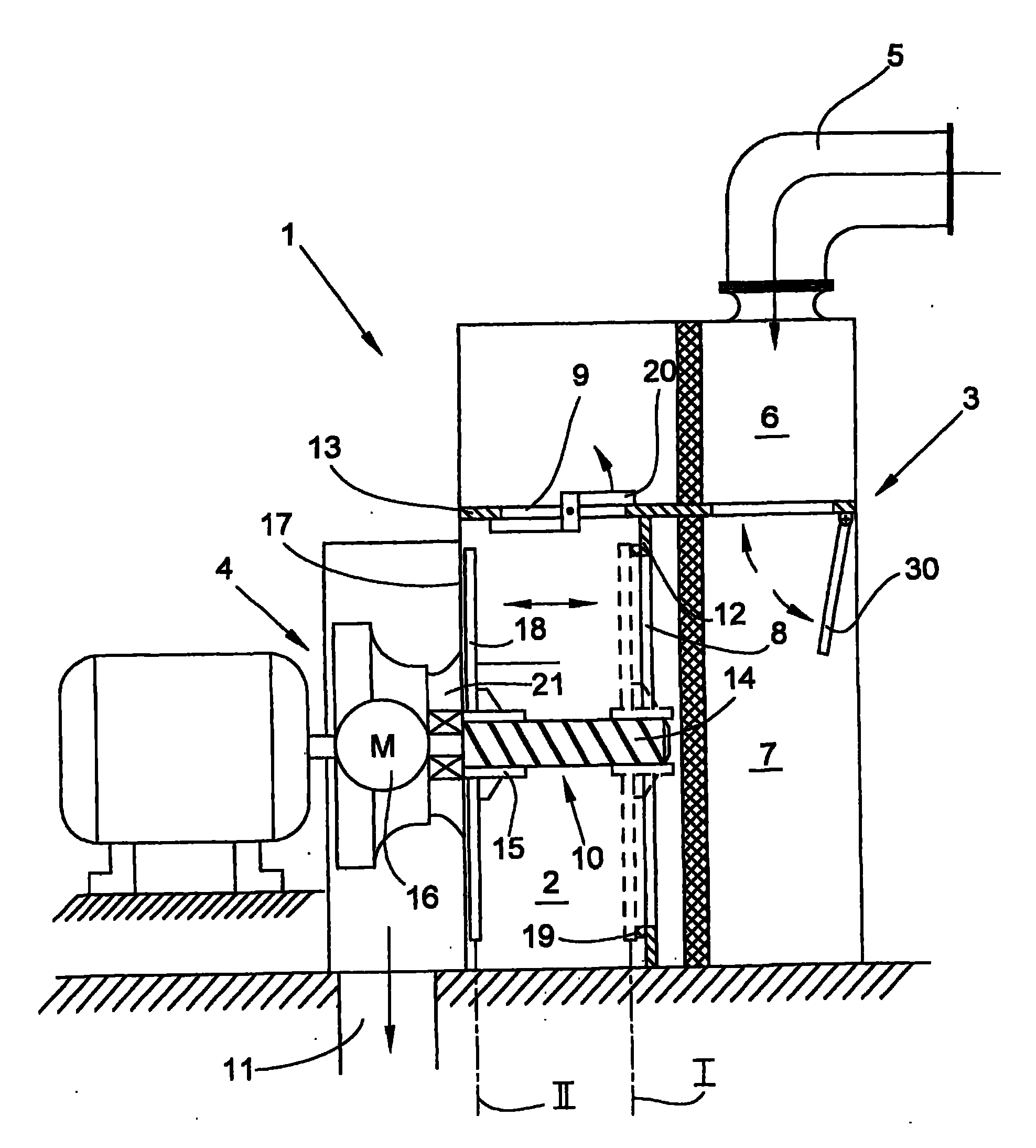
[0021] figure 1 A filter device of a textile machine for producing cross-wound bobbins shown in side view as an example in FIG. The filter device 1 is connected via a suction channel 5 shown schematically to a wind consumer (not shown) of the textile machine and via an exhaust channel 11 to a spinning mill-specific suction device. In the illustrated embodiment, the filter device 1 has two adjacently arranged identical filter chambers 3 , both of which are connected to an intermediate chamber 2 which is connected laterally to a vacuum source 4 . The filter chamber 3 is here divided into a main filter chamber 7 and a spare filter chamber 6, wherein the main filter chamber 7 is connected to the intermediate chamber 2 through the air passage hole 8 arranged in the partition 12, and the spare filter chamber 6 is connected to the intermediate chamber 2 through the air passage hole 8 in the partition 12. The air passage hole 9 in 13 is connected with the intermediate chamber 2 .

...


PUM


Abstract

The invention relates to a filter device for a textile machine for the production of cross-wound spools, comprising a filter chamber, an intermediate chamber separated by a partition wall from the filter chamber and a vacuum source connected with the intermediate chamber, wherein at least one air passage opening is arranged in the partition wall and closed by a closure device in a setting way. According to the invention, at least one air passage opening (8) comprises an almost complete open inner cross section and laterally offsets relative to an intake ring (21) of the vacuum source (4) and a compact closed device (10) is arranged in the area of the air passage opening (8) and the closure device (10) is axially movably mounted on a vertical guide piece (14) between two terminal positions (I,II) and the air passage opening (8) is closed at the closure position and the closure device (10) is positioned at the second terminal position (II) outside the suction air flow acting in the area of the air passage opening (8).

Description

technical field [0001] The invention relates to a filter device for a textile machine for producing cross-wound bobbins according to the preamble of claim 1 . Background technique [0002] Known textile machines for producing cross-wound bobbins, such as open-end rotor spinning machines, have a generally large number of wind consumers. Such textile machines are therefore usually equipped with machine-specific vacuum systems which provide the vacuum absolutely required for the spinning process in wind consumers such as open-end spinning machines. This machine-specific vacuum system has a vacuum source (e.g. an aspirator), a filter device positioned in front of the aspirator, and a suction channel along the longitudinal direction of the machine to which the individual free-end spinning devices are connected via branches . In the case of several such free-end rotor spinning machines, firstly the suction support beams for the wind supply of the mobile service unit and the aspi...

Claims


Application Information

Patent Timeline
Patent Type & Authority Applications(China)
IPC IPC(8): B01D46/10B01D46/42D01H11/00
CPCD01H11/005D01H11/00
Inventor 迈克尔·斯皮策
Owner OERLIKON TEXTILE GMBH & CO KG
Why Eureka
Try Eureka