Efficient energy-saving fan for conveying medium-flow and medium-high-pressure materials

A high-efficiency, energy-saving, high-pressure technology, applied in the components of pumping devices for elastic fluids, liquid fuel engines, mechanical equipment, etc., can solve problems such as increased vibration of fan bearings, affecting the dynamic balance of fans, and aggravating blades. , to achieve the effect of reducing wind loss, improving convenience and increasing strength

Pending Publication Date: 2021-09-03
ZHENJIANG DANTU DISTRICT FOOD FACTORY
View PDF0 Cites 0 Cited by
  • Summary
  • Abstract
  • Description
  • Claims
  • Application Information

AI Technical Summary

Problems solved by technology

[0005] The purpose of the present invention is to provide a high-efficiency and energy-saving fan for medium flow and medium-high pressure material delivery to solve the problem that the windward surface of the blade is continuously rubbed and impacted by solid particles when the existing fan proposed in the background technology is transporting materials , will lead to the wear of the blades, and at the same time, when transporting some corrosive gases, it will aggravate the erosion and wear of the blades. The wear of the blades will affect the dynamic balance of the fan, which will gradually increase the vibration of the fan bearing and increase the noise. Timely maintenance will cause serious safety accidents

Method used


Image

  • Efficient energy-saving fan for conveying medium-flow and medium-high-pressure materials
  • Efficient energy-saving fan for conveying medium-flow and medium-high-pressure materials
  • Efficient energy-saving fan for conveying medium-flow and medium-high-pressure materials

Examples


Embodiment Construction

[0028] The following will clearly and completely describe the technical solutions in the embodiments of the present invention with reference to the accompanying drawings in the embodiments of the present invention. Obviously, the described embodiments are only some, not all, embodiments of the present invention. Based on the embodiments of the present invention, all other embodiments obtained by persons of ordinary skill in the art without making creative efforts belong to the protection scope of the present invention.

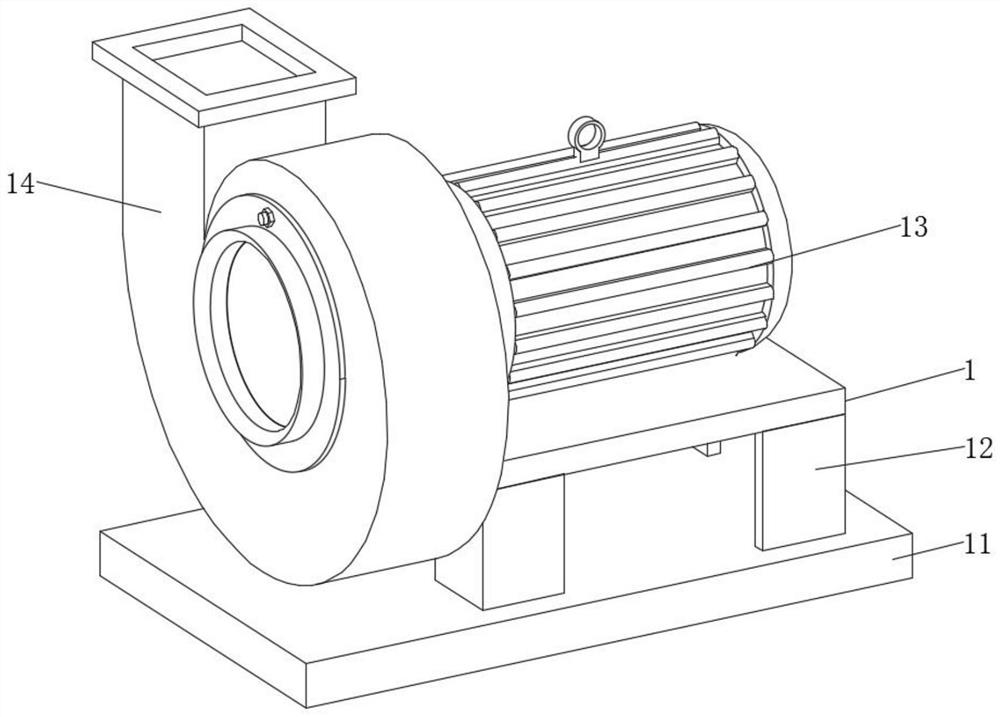
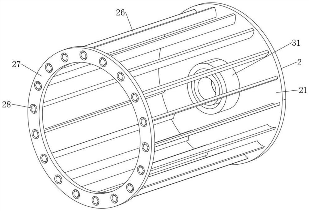
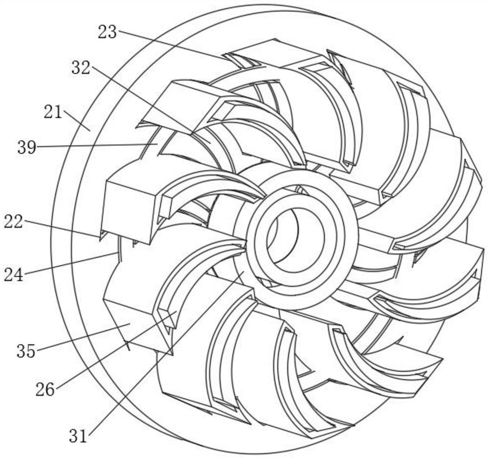
[0029] see Figure 1-8 , an embodiment provided by the present invention: a high-efficiency energy-saving fan for medium-flow, medium-high pressure material conveyance, including a fan body 1, the fan body 1 includes a base 11, a bracket 12 is fixedly installed on the top surface of the base 11, and the bracket The top surface of 12 is fixedly installed with motor 13, and the front side of bracket 12 is fixedly connected with organic casing 14, and the inside ...


PUM


Abstract

The invention relates to the technical field of material conveying fans, in particular to an efficient energy-saving fan for conveying medium-flow and medium-high-pressure materials. The efficient energy-saving fan comprises a fan body, the fan body comprises a base, a support is fixedly mounted on the top surface of the base, a motor is fixedly mounted on the top surface of the support, a shell is fixedly connected to the front side of the support, an impeller body is movably installed in the fan body and comprises a blade disc, the front end of the motor is fixedly connected with the blade disc, a first mounting groove is formed in the front face wall of the blade disc, and a second mounting groove is formed in the left side of the first mounting groove. According to the fan, a protection structure is arranged, the surfaces of the blades can be protected, the strength of the blades is effectively improved, the service life of the blades is prolonged, meanwhile, when a protection shell is replaced, only a single set needs to be replaced, the whole set does not need to be replaced, and therefore the maintenance cost is saved, and the productivity is improved.

Description

technical field [0001] The invention relates to the technical field of material conveying fans, in particular to a high-efficiency and energy-saving fan for medium-flow, medium-high pressure material conveying. Background technique [0002] A centrifugal fan is a driven fluid machine that relies on input mechanical energy to increase the gas pressure and discharge the gas. Centrifugal fans are widely used in ventilation, dust removal and cooling of factories, mines, tunnels, cooling towers, vehicles, ships and buildings; ventilation and induction of boilers and industrial furnaces; cooling and cooling of air conditioning equipment and household appliances Ventilation; drying and sorting of grain, etc. The centrifugal fan is based on the principle of converting kinetic energy into potential energy. It uses a high-speed rotating impeller to accelerate the gas, then decelerates, changes the flow direction, and converts kinetic energy into potential energy (pressure). In a sin...

Claims


Application Information

Patent Timeline
Patent Type & Authority Applications(China)
IPC IPC(8): F04D25/06F04D29/30F04D29/00F04D29/62F04D29/66
CPCF04D25/0606F04D29/30F04D29/289F04D29/002F04D29/626F04D29/667
Inventor 徐洋
Owner ZHENJIANG DANTU DISTRICT FOOD FACTORY
Why Eureka
Try Eureka