
Lifter for main roller and method for transporting the main roller

A technology of lifts and motors, applied in the field of lifts, can solve problems such as poor workability, long working time, and difficulty in positioning the weight of work, and achieve the effects of reasonable operation, efficient installation, efficient installation or disassembly operations

Inactive Publication Date: 2014-07-09
KOMATSU NTC LTD
View PDF7 Cites 0 Cited by
  • Summary
  • Abstract
  • Description
  • Claims
  • Application Information

AI Technical Summary

Problems solved by technology

[0004] However, when the main roller is heavy, it cannot be rolled on the roller support table 165 or on the guide rails 62A, 62B, and workability is very poor in this state.
In addition, the positioning work of the processing rollers 115, 116, 117 with respect to the bearing unit is also difficult due to the weight, and there is a problem in work efficiency that this work takes a long time.

Method used


Image

  • Lifter for main roller and method for transporting the main roller
  • Lifter for main roller and method for transporting the main roller
  • Lifter for main roller and method for transporting the main roller

Examples


Embodiment Construction

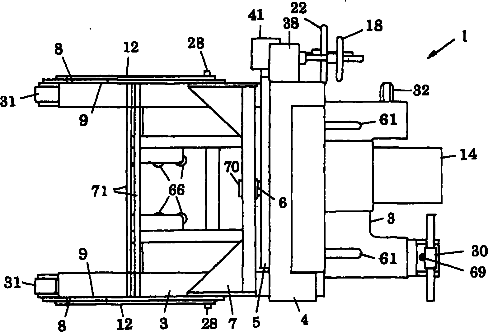
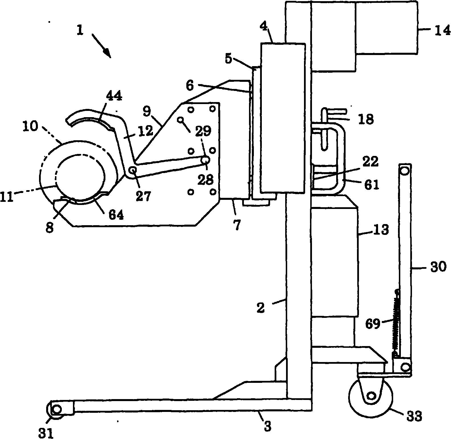
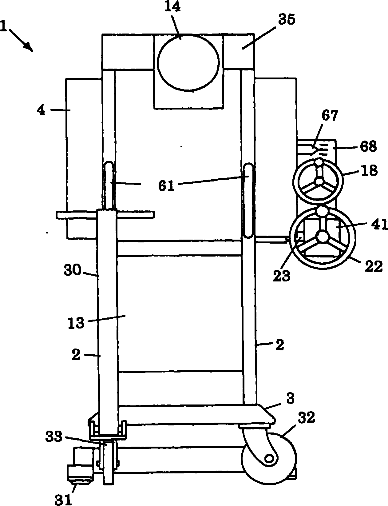
[0033] Figure 1 to Figure 3 shows the overall structure of the main roll lifter 1 according to the present invention, Figure 4 to Figure 9 Indicates the structure of each part. Such as Figure 1 to Figure 3 As shown, the main roller lifter 1 is used to support the main roller 10 of the wire saw as the conveying and holding object, and has: a moving vehicle 3, an elevating part 4, a lateral moving part 5, a horizontal extending part 7, and a pair of forks. 9, and pressing bar 12.

[0034] The mobile vehicle 3 is a traction or hand-push type, and is composed of a fixed wheel 31 located at the front left and right position, a caster wheel 32 located at the rear left and right position, and a free wheel 33 with a handle 30 on the other side that can change the direction. , there is a pair of left and right pillars 2 for lifting guidance at a slightly rear position. The handle 30 is pre-tensioned by a tension spring 69 to keep it upright. Moreover, the handle 61 for hand pus...


PUM


Abstract

The invention provides a lifter for a main roller and method for transporting the main roller, capable of easily adjusting the height direction and the horizontal direction of the main roller, when lifting or transporting the main roller and mounting or demounting the main roller relative to a bearing unit of a linear saw. The lifter for the main roller comprises: a moving vehicle with a pillar for lifting and guiding; a lifting part supported on the pillar and capable of freely lifting along the pillar; a horizontal moving part supported on the lifting part and capable of horizontally moving; a horizontal protruding part capable of freely asway being supported on the horizontal moving part using the support axle of the horizontal direction; a pair of support forks mounted on the horizontal protruding part and comprising roller support parts for supporting fork ends at the two ends of the main roller of the linear saw as the transporting and keeping object; and a pressing rod for pressing the fork ends on the roller support parts of the support forks.

Description

technical field [0001] The present invention relates to a lifter used when holding and conveying a main roller of a wire saw, when attaching the main roller to a bearing unit of a wire saw, and when detaching the main roller from a bearing unit of a wire saw, and utilizing The main roller conveying method of the elevator. Background technique [0002] As a wire saw, a wire rod is wound multiple times between a plurality of main rollers, and the running wire rod is brought into contact with a workpiece such as a semiconductor, thereby cutting the workpiece to a predetermined thickness. When assembling this wire saw, there is a work of attaching the main roller to the bearing unit. Also, on the user side of the wire saw, when the main roller is worn or the cutting specifications of the workpiece are changed, there is work to remove the main roller from the bearing unit of the main roller and attach another main roller to the bearing unit. [0003] Patent Document 1 discloses...

Claims


Application Information

Patent Timeline
Patent Type & Authority Patents(China)
IPC IPC(8): B24B27/06
CPCB24B27/06B66C1/62B66F9/07504B66F9/14B66F9/18B66F9/184
Inventor 长谷川洋介具志坚仁阿部克彦小林茂雄
Owner KOMATSU NTC LTD
Learn More