Heating vibration screw extractor

A vibrator and heater technology, applied in the field of pullers, can solve problems such as difficulty in disassembly, and achieve the effects of reducing equipment costs, reducing volume and weight, and protecting safety

Inactive Publication Date: 2012-02-08
TAIYUAN COAL GASIFICATION GROUP
View PDF0 Cites 0 Cited by
  • Summary
  • Abstract
  • Description
  • Claims
  • Application Information

AI Technical Summary

Problems solved by technology

[0004] In order to solve the problem that the existing puller is difficult to disassemble some fastening parts on the shaft with tight fit, the present invention provides a heating and vibrating puller

Method used


Image

  • Heating vibration screw extractor
  • Heating vibration screw extractor
  • Heating vibration screw extractor

Examples


Embodiment 1

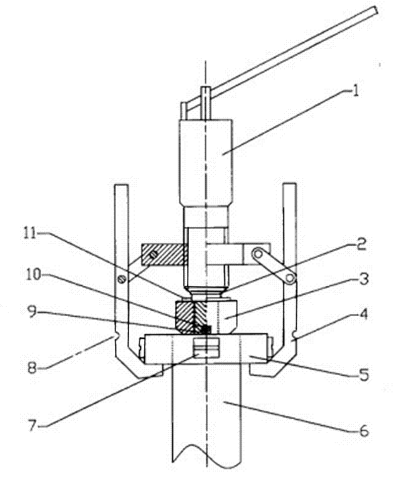
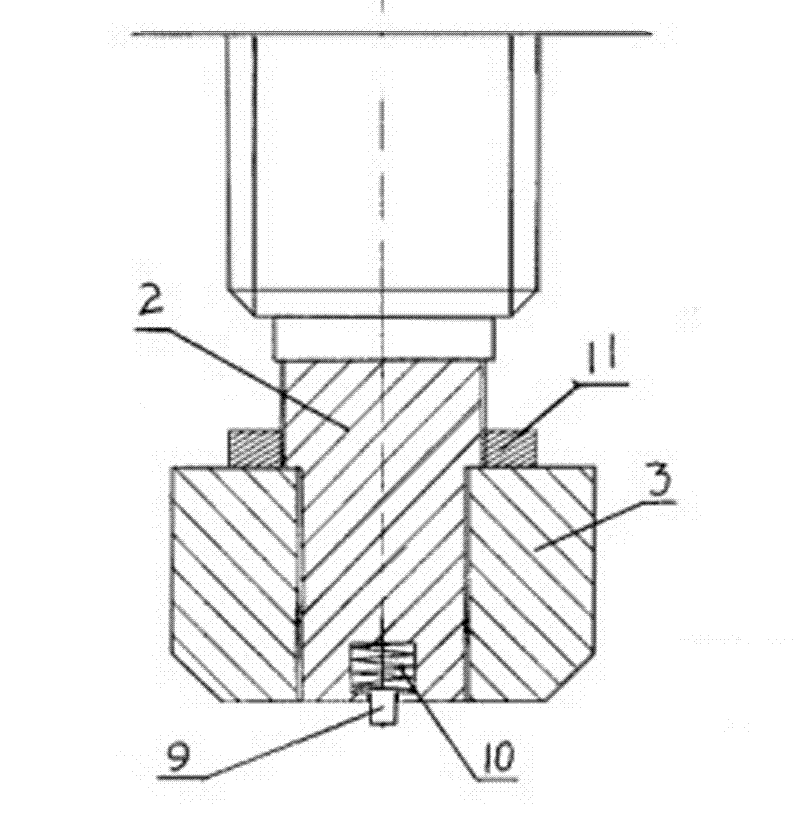
[0013] Such as image 3 , 4 As shown, the heating vibration puller includes a push rod 2 and a claw 4 connected with the push rod 2. A vibrator 3 with adjustable vibration frequency is installed at the end of the push rod 2, and also includes a set of high-frequency induction heating device 7, and one end of each high-frequency induction heater 7 is equipped with a magnet. In this specific embodiment, the push rod 2 is in the form of a jack 1 .

[0014] Described high-frequency induction heater 7 adopts existing product. The vibrator 3 with adjustable vibration frequency adopts existing products, and the vibrator 3 with adjustable vibration frequency is made into a ring shape, and the end of the ejector rod 2 is provided with radial tapered steps, and 3 sets of ring-shaped vibrator On the tapering part at the end of the ejector rod 2, a preloading ring 11 threaded with the non-reducing part of the ejector rod is sleeved on the ejector rod 2. When in use, the preloading ring...

Embodiment 2

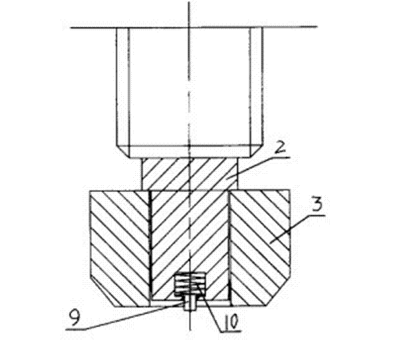
[0019] Such as figure 1 , 2 As shown, the vibrating puller includes a push rod 2 and a claw 4 connected to the push rod 2. A vibrator 3 with adjustable vibration frequency is installed at the end of the push rod 2, and also includes a group of high-frequency induction heaters. 7. A magnet is installed at one end of each high-frequency induction heater 7 . In this specific embodiment, the push rod 2 is in the form of a jack 1 .

[0020] Described high-frequency induction heater 7 adopts existing product. The vibrator 3 with adjustable vibration frequency adopts existing products, and the vibrator 3 with adjustable vibration frequency is made into a ring shape, and the end of the ejector rod 2 is provided with radial tapered steps, and 3 sets of ring-shaped vibrator On the tapered portion at the end of the ejector rod 2, the length of the tapered portion of the ejector rod is less than the thickness of the annular vibrator and the difference between the thickness of the annul...


PUM


Abstract

The invention relates to a screw extractor, in particular to a heating vibration screw extractor. The invention solves the problem that the existing screw extractor is hard to disassemble some shaft fastening pieces with tight fitness. The heating vibration screw extractor comprises a mandrel and a falcula connected with the mandrel, wherein a vibrator with adjustable vibration frequency is arranged on the top of the mandrel; the screw extractor also comprises a group of high frequency induction heaters, wherein a magnet is arranged on one end of each high frequency induction heater. When in use, the high frequency induction heaters heat the outer surfaces of the parts to be disassembled so as to reduce the interference degree between the parts to be disassembled; and the parts to be disassembled perform strong resonance vibration under the action of the vibrator so as to greatly reduce the friction force between the parts to be disassembled. In order to solve the situation that the friction force between the parts to be disassembled is too large, the vibrator is installed on the mandrel of the screw extractor of the invention to perform forced vibration of the parts to be disassembled and the heating device is added on the screw extractor, thus greatly reducing the friction force between the parts to be disassembled and solving the condition that the original screw extractor is hard to be used for disassembly.

Description

technical field [0001] The invention relates to a puller, in particular to a heating and vibrating puller. Background technique [0002] The puller is also called the jack puller, which is widely used to disassemble the fastening parts on the shaft such as various couplings, gears, bearings, pulleys, etc. It consists of two parts: the ejector rod and the claw connected (or hinged) with the ejector rod , The ejector rod is divided into two types: screw rod and jack, and the hook claw is divided into two types: two-claw type and three-claw type. Make the ejector rod move forward steadily, and the claw hook retreats accordingly, pulling out the object to be pulled. [0003] Existing pullers are very convenient and effective when disassembling fastening parts on shafts with looser fits, but it is sometimes very difficult to disassemble fastening parts on shafts with tighter fits, especially larger parts. The assembly interference between the disassembled parts is too large, re...

Claims


Application Information

Patent Timeline
Patent Type & Authority Patents(China)
IPC IPC(8): B25B27/00
Inventor 白文政宋旗跃王兆文李建全刘承东李永林孟祥俊王安宇王立峰范虹聂嘉汾
Owner TAIYUAN COAL GASIFICATION GROUP
Why Eureka
Try Eureka