Self-locking mechanism for upper pressure beam of broken tape protection device

A protection device and self-locking technology, which is applied in the direction of conveyor control devices, conveyor objects, transportation and packaging, etc., can solve problems such as inconvenient use, inconvenient production, and affecting the normal operation of the conveyor, so as to improve work efficiency and reduce troublesome effect

Inactive Publication Date: 2010-09-15
徐州中部矿山设备有限公司
View PDF6 Cites 0 Cited by
  • Summary
  • Abstract
  • Description
  • Claims
  • Application Information

AI Technical Summary

Problems solved by technology

[0002] According to the installation experience and market survey, the upper pressure beam naturally droops and touches the coal on the conveyor belt before the broken belt protection device of the belt conveyor is put into use after installation, which affects the normal operation of the conveyor
In order not to affect the production, the user must fix the up

Method used


Image

  • Self-locking mechanism for upper pressure beam of broken tape protection device
  • Self-locking mechanism for upper pressure beam of broken tape protection device
  • Self-locking mechanism for upper pressure beam of broken tape protection device

Examples


Example Embodiment

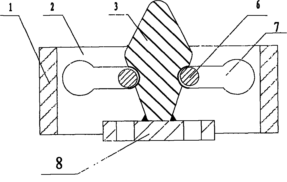
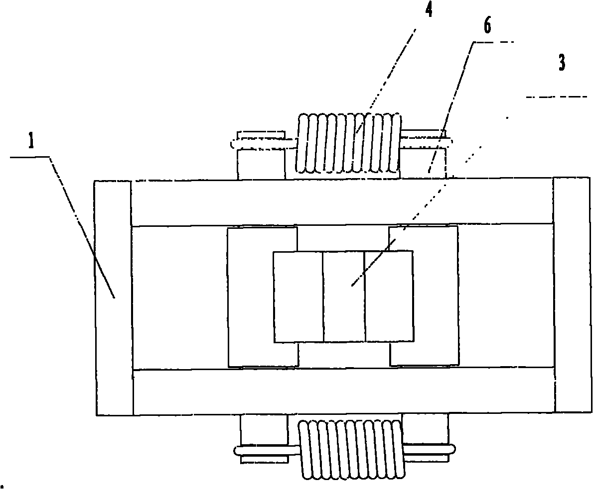
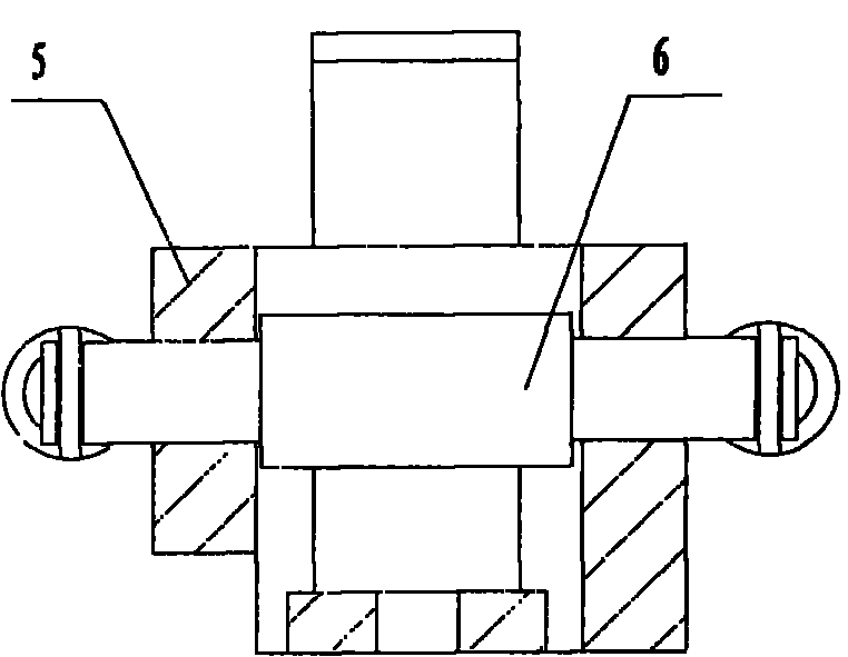
[0011] Such as figure 1 , figure 2 with image 3 As shown, the two ends of the side plates 1 in the pressure beam self-locking mechanism of the upper strap protection device are welded to a left slideway plate 2 and a right slideway plate 5 to form a self-locking square box. The two self-locking shafts 6 are respectively placed in the slideway 7 of the left slideway plate 2 and the right slideway plate 5, and the two ends are connected and tightened by the tension spring 4. The self-locking plate 3 is welded to the supporting base plate 8 and fixed with the upper pressure beam of the broken belt protection device by bolts.

[0012] The working principle is: when the self-locking plate 3 moves up with the upper pressure beam, it hits the self-locking shaft 6, and at this time, the self-locking shaft 6 moves to both sides to open. When the upper pressure beam rises to the limit, the self-locking shaft 6 slides into the self-locking groove in the self-locking plate, tightly locks ...


PUM


Abstract

The invention discloses a self-locking mechanism for an upper pressure beam of a broken tape protection device, which comprises two lateral plates, a left slideway plate, a right slideway plate, two self-locking shafts, two tension springs, a self-locking plate and a weight-bearing soleplate, wherein a slideway slot is respectively arranged on the left slideway plate and the right slideway plate, and a self-locking slot which is matched with the inner ends of the slideway slots on the left slideway plate and the right slideway plate is arranged on the self-locking plate; the left slideway plate and the right slideway plate are fixed between the two lateral plates at both ends to form a self-locking square box; the two self-locking shafts are respectively installed in the slideways of the left slideway plate and the right slideway plate, and both ends of each self-locking shaft are tensed through the tension springs; and the self-locking plate is fixed on the weight-bearing soleplate. The self-locking plate and the weight-bearing soleplate form a weight-bearing assembly and are fixed together with the upper pressure beam of the broken tape protection device. The invention has the advantages that the upper pressure beam can not slide downwards due to the external leakage of oil pressure and performs a protection action for the safe use of equipment.

Description

technical field [0001] The invention relates to a broken belt protection device for a belt conveyor, in particular to an upper pressure beam self-locking mechanism of the broken belt protection device. Background technique [0002] According to installation experience and market research, the upper pressure beam naturally droops and touches the coal on the conveyor belt before the broken belt protection device of the belt conveyor is put into use after installation, which affects the normal operation of the conveyor. In order not to affect the production, the user must fix the upper pressure beam with iron wire or other methods before the equipment is put into use, which brings inconvenience to the production of the user. After being put into use, because the oil pressure will leak, the upper pressure beam will also sag, and the user needs to perform a reset action every once in a while, which also brings certain inconvenience to the use. Contents of the invention [0003...

Claims


Application Information

Patent Timeline
IPC IPC(8): B65G43/00
Inventor 王锟尚玉征
Owner 徐州中部矿山设备有限公司
Why Eureka
Try Eureka