Special lifting tool for steel containment vessel of nuclear power station and lifting method

A technology for steel containment and nuclear power plants, which is used in measuring devices, transportation and packaging, load hoisting components, etc., can solve problems such as hoisting difficulties, and achieve the effects of ensuring hoisting quality and safety, facilitating transportation, and eliminating manufacturing deviations.

Active Publication Date: 2010-09-15
CHINA NUCLEAR IND FIFTH CONSTR CO LTD
View PDF2 Cites 31 Cited by
  • Summary
  • Abstract
  • Description
  • Claims
  • Application Information

AI Technical Summary

Problems solved by technology

The characteristics of the above-mentioned steel containment components make it very difficult to hoist. On the one hand,

Method used


Image

  • Special lifting tool for steel containment vessel of nuclear power station and lifting method
  • Special lifting tool for steel containment vessel of nuclear power station and lifting method
  • Special lifting tool for steel containment vessel of nuclear power station and lifting method

Examples


Embodiment 1

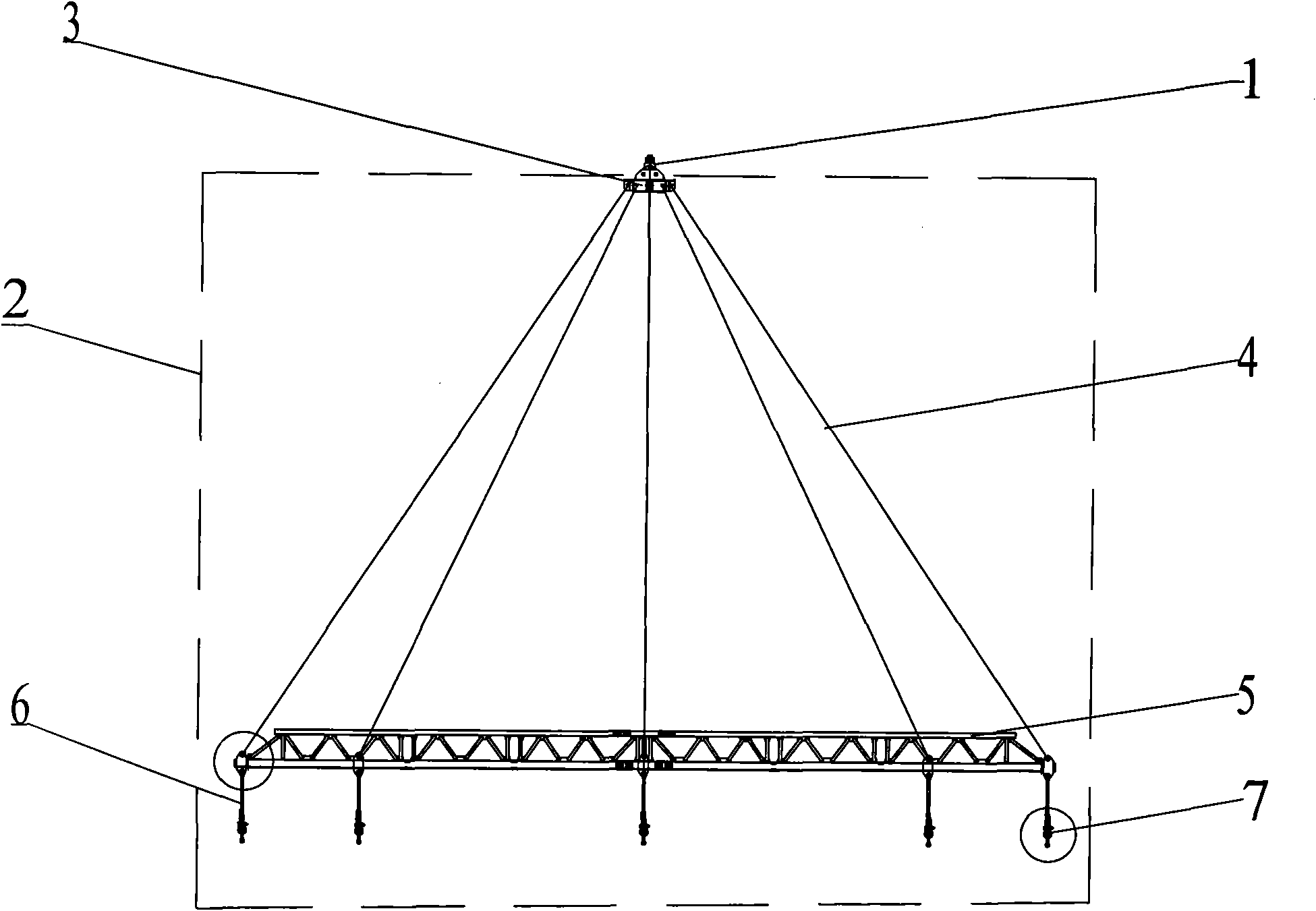
[0047] The most important design of the special spreader for the steel containment of the present invention is that a sling transition beam 3 is arranged in the special spreader 2 . The sling transition beam 3 is composed of four lug plates 31 , an upper cover plate 32 , a connecting plate 33 and a lower cover plate 34 . The lifting lugs 31 are fixed on the upper surface of the upper cover plate 32 and are connected with the hanger 1 of the crane, and the lifting lugs 31 are connected in pairs by reinforcing ribs 35 . The upper cover 32 and the lower cover 34 are fixedly connected by a connecting plate 33 . The connecting plate 33 of the sling transition beam 3 is composed of two through plates 331 and four short plates 332, which are connected to each other to form a "meter"-shaped structure. Through the transition connection of the suspension beam 3, there are eight balanced force points on the suspension beam 5, thereby ensuring the safety of the suspension beam 5 during t...

Embodiment 2

[0050]Another preferred structure of the sling transition beam 3 of the present invention is composed of two lug plates 31 , an upper cover plate 32 , a connecting plate 33 and a lower cover plate 34 . Both lug plates 31 are provided with a pin hole, and the length of the lug plates 31 is the same as the diameter of the upper cover plate 32 . Ribs 35 are also provided on both sides of the lug plate 31 to play a role of stable support. The structure of the connecting plate 33 is the same as the preferred embodiment 1 of the suspension cable transition beam.

[0051] The structural forms of the above embodiments of the suspension cable transition beam are not limiting. On the basis of the above embodiments, the structure of the lug plate 31 and the connecting plate 33 of the sling transition beam can be adjusted according to the structure of the sling attached to the crane.

[0052] Preferred embodiment of hanging beam 1

[0053] In order to evenly distribute the eight stress...


PUM


Abstract

The invention relates to a special lifting tool for a steel containment vessel of a nuclear power station and a lifting method. A special lifting tool for the steel containment vessel of the nuclear power station comprises a sling transition beam, at least eight riggings, a lifting beam and at least eight adjustable devices, wherein the sling transition beam is fixedly connected with the lifting beam through the rigging; and the adjustable devices are symmetrically distributed at the top end of the lifting beam. In the lifting method of the steel containment vessel of the nuclear power station, a special tool is applied as transition connection between the lifting tool of a crane and the components of the steel containment vessel of nuclear power station; before lifting, load test is carried out on the sling transition beam, riggings, the lifting beam, the adjustable devices and transition connecting tools; during lifting, the length of each adjustable device is adjusted according to the detected stress data thereof by using a stress detection technology until each adjustable device reaches the stress balance requirement. The special lifting tool and the lifting method of the invention can realize stress balance of each component of the steel containment vessel during lifting, prevent component deformation and guarantee safety.

Description

technical field [0001] The invention relates to a special hoisting tool and a hoisting method for large-scale equipment, in particular to a special hoisting tool and a hoisting method for hoisting steel containment shells of nuclear power plants. Background technique [0002] The containment vessel is a container for a nuclear reactor and some safety systems. Its purpose is to completely isolate nuclear power equipment from the external environment and to achieve safety. [0003] China's Sanmen Nuclear Power Plant is the world's first AP1000 third-generation nuclear reactor. The AP1000 reactor type designed by Westinghouse Corporation of the United States has a double-layer containment structure, the outer layer is prestressed concrete, and the inner layer is steel plate structure. Containment shell. The steel containment vessel of a nuclear power plant is divided into six components: the bottom head, the first ring of the cylinder, the second ring of the cylinder, the thir...

Claims


Application Information

Patent Timeline
IPC IPC(8): B66C1/12G01L1/22
Inventor 梁选翠王卫忠李灿彬莫晓军杜庆生滕儒民王伟石磊王欣王荣敏吴杰包国生
Owner CHINA NUCLEAR IND FIFTH CONSTR CO LTD
Why Eureka
Try Eureka