Antimagnetic particle three-dimensional control device based on MEMS technology

A technology for manipulating devices and magnetic particles, which is applied in the field of special equipment in the field of life science and technology, can solve the problems of particle activity, restricting the application of diamagnetic technology, particle pollution, etc. Effect

Inactive Publication Date: 2010-09-15
SHANGHAI JIAO TONG UNIV
View PDF4 Cites 0 Cited by
  • Summary
  • Abstract
  • Description
  • Claims
  • Application Information

AI Technical Summary

Problems solved by technology

[0003] The existing micro-manipulation of anti-magnetic particles uses contact-type mechanical micro-clamps, non-contact optical tweezers, etc. Contact-type manipulation is easy to pollute the particles and affect the activity of the particles. Magnetic clamp-type manipulation requires a third party, namely magnetic microspheres. , it is not applicable to occasions where diamagnetic particles need to be directly manipulated. The diamagnetic micromanipulation based on the magnetic Archimedes effect can realize non-contact and non-damaging diamagnetic particle micromanipulation. The magnetic source in this technology is mainly composed of permanent magnets, The electric coil or the combination of the two forms. When the permanent magnet is used to generate the magnetic field environment, the magnetic field is not variable. Only the mechanical structure can be used to drive the position of the permanent magnet to change the magnetic field distribution, which is not conducive to miniaturization and portability, and only the electric coil is used. In a magnetic field environment, the strength of the magnetic field is limited, which limits the application of anti-magnetic technology. How to combine the application of the two and realize the miniaturization and portability of the micro-manipulation system has become a research hotspot.
So far, there are no related reports

Method used


Image

  • Antimagnetic particle three-dimensional control device based on MEMS technology
  • Antimagnetic particle three-dimensional control device based on MEMS technology
  • Antimagnetic particle three-dimensional control device based on MEMS technology

Examples


Embodiment Construction

[0020] The embodiments of the present invention are described in detail below. This embodiment is implemented on the premise of the technical solution of the present invention, and detailed implementation methods and specific operating procedures are provided, but the protection scope of the present invention is not limited to the following implementation example.

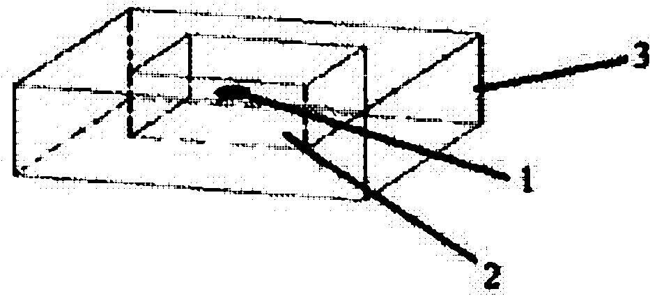
[0021] Such as figure 1 with figure 2 As shown, the present embodiment includes: diamagnetic particles 1, paramagnetic solution 2, chamber 3, permanent magnet 4 and chip 5, wherein: diamagnetic particle 1 is located in the paramagnetic solution 2, and paramagnetic solution 2 is provided in the chamber 3. The magnetic solution 2, the permanent magnet 4 is adhered on the chip 5, and the chamber 3 is placed on the permanent magnet 4.

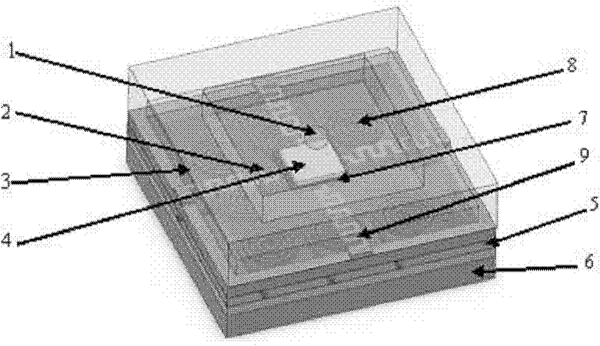
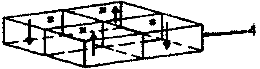
[0022] Such as Figure 4 As shown, the chip 5 includes: a base 6, a load platform 7, a coil array 8 and a spring 9, wherein: the base 6 is photolithographically provided with a coil...


PUM


Abstract

The invention relates to an antimagnetic particle three-dimensional control device based on the MEMS technology in the life science technical field, comprising paramagnetism solution, a chamber, a permanent magnet and a chip; wherein the chip comprises a substrate, a load platform, a coil array and a spring, wherein the substrate is provided with the coil array, the load platform and the spring in a photoetching way, one end of the spring is fixed on the substrate, the other end is connected with the load platform, the permanent magnet is adhered on the load platform, the chamber is internally provided with the paramagnetism solution, and the chamber is placed on the permanent magnet. The magnetic source driving of the invention adopts flexible electromagnetic drive mode, structure is simple, MEMS process is adopted, and the device can be made into a portable on-chip system with low cost.

Description

technical field [0001] The invention relates to a special equipment in the technical field of life sciences, in particular to a three-dimensional antimagnetic particle manipulation device based on MEMS technology. Background technique [0002] In the field of anti-magnetic levitation, the capture and movement of anti-magnetic particles under non-contact and non-damaging conditions is the basis for realizing the manipulation of anti-magnetic objects, and the change of magnetic source is an important guarantee for the translation and steering of anti-magnetic particles. It is to regulate the shape and gradient of the spatial magnetic field. An important field of application of anti-magnetic levitation technology is the field of life sciences. Therefore, the realization of miniaturization and portability of the magnetic source driving method is of great significance for the promotion of the application of anti-magnetic levitation technology in the field of life sciences. import...

Claims


Application Information

Patent Timeline
Patent Type & Authority Applications(China)
IPC IPC(8): B81C1/00
Inventor 张卫平李世鹏陈文元刘武胡牧风
Owner SHANGHAI JIAO TONG UNIV
Why Eureka
Try Eureka