
Lifting anti-winding flag pole

A flagpole and lifting system technology, applied in the field of flagpoles for hanging flags, can solve the problems of undignified and unsightly

Inactive Publication Date: 2010-09-15
宋铁芳
View PDF6 Cites 8 Cited by
  • Summary
  • Abstract
  • Description
  • Claims
  • Application Information

AI Technical Summary

Problems solved by technology

[0004] The present invention solves the problem of unsightly and undignified flag winding and lifting ropes exposed outside the flagpole due to changes in wind direction

Method used


Image

  • Lifting anti-winding flag pole

Examples


Embodiment Construction

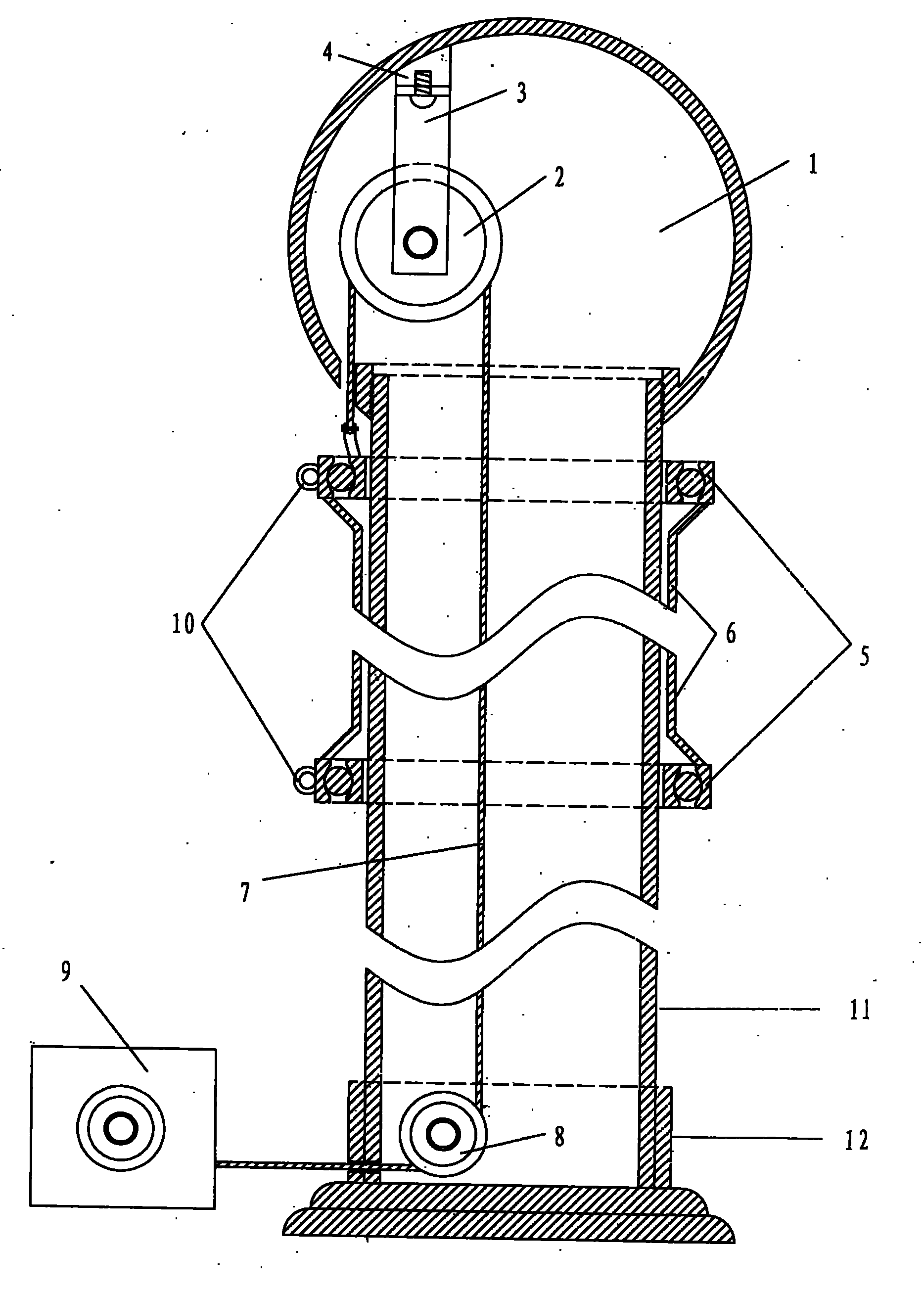
[0008] The essence of the anti-winding flagpole is the anti-winding frame and built-in lifting system. The entire anti-winding flagpole is composed of five parts: a spherical crown body, a flagpole, an anti-winding frame, a lifting system and a base.

[0009] Fixed frame 4 is arranged in spherical crown body 1, and fixed frame 4 is fixed pulley frame 3 and fixed pulley 2 with screw. There is a spiral opening on the inner side of the lower gap of the spherical crown body, which is docked and fixed with the upper spiral opening of the flagpole 11 .

[0010] The outside of the flagpole 11 is an anti-winding frame.

[0011] There is a certain gap between the bearing inner axle sleeve 5 and the flagpole 11 of the anti-winding frame. The anti-tangle frame slides vertically on the flagpole under the control of the rope and the winch. The outer bearing sleeves of the two bearings are symmetrically connected by two connecting plates (the length of the connecting plates is the height...


PUM


Abstract

Commonly used flag poles are divided into two classes according to using methods, namely a lifting flag pole of which the upper end is provided with a fixed pulley and on which a flag is usually lifted by using a rope, and a fixed flag pole on which the flag is not easy to replace after the flag is directly hung on the flag pole. The invention discloses the lifting flag pole. The invention relates to the technical field of flag poles which do not wind the flags in any wind direction. Moreover, after the flag is lifted, the rope for lifting the flag cannot be seen from the outside. The technical background comprises that in most current lifting flag poles, the fixed pulley is placed at the tail end of the flag pole, and the flag is lifted and suspended through the rope hung on the fixed pulley. The invention solves the problem that the flag pole is unaesthetic and undignified because the flag is wound and the lifting rope is naked outside the flag pole due to the change of the wind direction. The total design comprises that a fixed pulley is arranged in a spherical crown body at the top end of the flag pole, and the spherical crown body opposite to the lower part of a pulley groove is provided with a rope passage so that one end of the rope can pass to get the outside of the flag pole. A flag anti-winding device is linked under the rope. The upper and lower end parts of the anti-winding device are provided with two special-shaped bearings which are sleeved outside the flag pole (inner sleeves of the bearings are slightly thicker than the flag pole, and have certain clearance so that the device slides on the flag pole). Outer shaft sleeves of the two bearings are connected by two symmetrical connecting plates, and the outer shaft sleeves and the connecting plates can rotate freely and horizontally. The problem that the flag is wound on the flag pole is solved by using tension of wind and free rotation.

Description

[0001] The flagpoles we usually use are divided into two types according to the method of use. One is that the upper end of the flagpole is equipped with a fixed pulley, and the flagpole that uses the rope to frequently lift the flag is called a lifting flagpole; The flagpole that can easily replace the flag is called fixed. This article is about the lifting flagpole. technical field [0002] The invention relates to a flagpole for hanging flags, in particular to a flagpole which does not wind around flags in any wind direction. And after the flag is raised, the flagpole of the rope for raising and lowering the flag cannot be seen outside. technical background [0003] Most of the elevating flagpoles we use now place a fixed pulley on the top of the flagpole, and the flag is lifted and suspended by extending the rope hanging on the fixed pulley. Contents of the invention [0004] The invention solves the problems of unsightly and undignified flag winding and lifting rope...

Claims


Application Information

Patent Timeline
Patent Type & Authority Applications(China)
IPC IPC(8): E04H12/32
Inventor 宋铁芳
Owner 宋铁芳
Learn More