Quick valve connecting device for gas-fired equipment

A quick connection and valve technology, which is applied in the field of connection devices connecting gas circuits between control valves and quick connection devices for valves used in gas equipment, can solve problems such as inconvenient installation and improper connection, and achieve convenient connection, maintenance and replacement, Create a convenient effect

Inactive Publication Date: 2010-09-15
PROCOM ELECTRIC APPLIANCES SHANGHAI
View PDF3 Cites 2 Cited by
  • Summary
  • Abstract
  • Description
  • Claims
  • Application Information

AI Technical Summary

Problems solved by technology

[0003] The purpose of the present invention is to design a valve quick connection device for gas equipment in view of the inconvenience of installation caused by connecting the valves of the existing gas equipment through connecting pipes, and the easy connection is not in place.

Method used


Image

  • Quick valve connecting device for gas-fired equipment
  • Quick valve connecting device for gas-fired equipment
  • Quick valve connecting device for gas-fired equipment

Examples


Embodiment 1

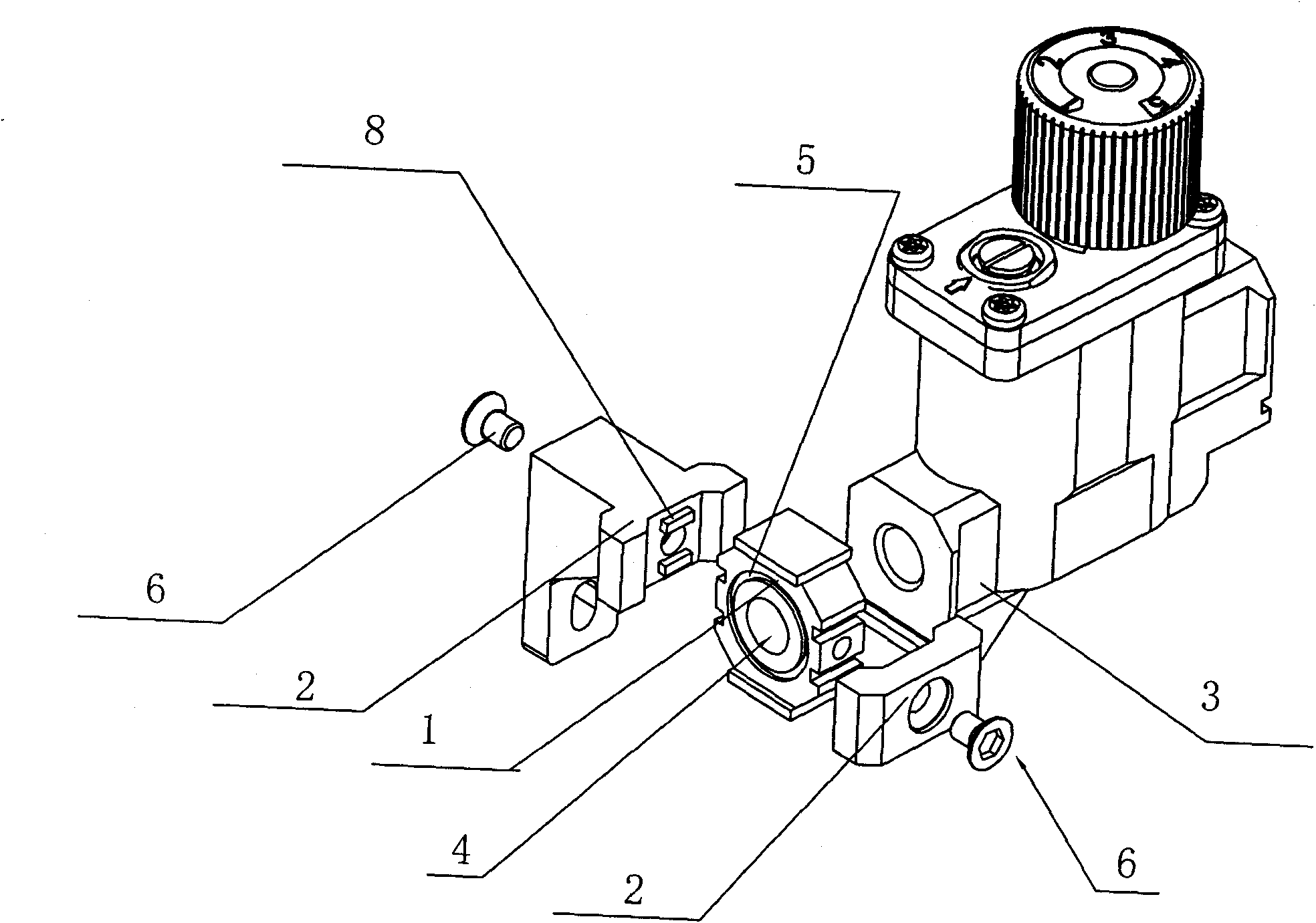
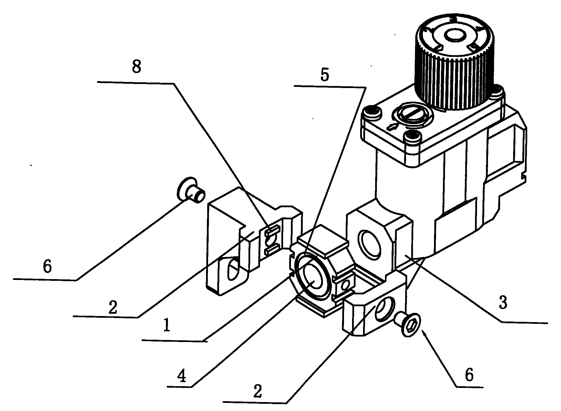
[0023] Such as figure 1 shown.

[0024] A valve quick connection device for gas equipment, which is mainly composed of a connecting piece 1 and two fastening pieces 2. The upper bottom surface or the lower bottom surface of the connecting piece 1 can be designed as a plane shape. From the perspective of reliable connection, the two fastening pieces Parts 2 can be respectively located on the front and rear surfaces or the upper and lower surfaces of the connecting part 1. The shapes or safety of the two fasteners 2 are the same, and there may be certain differences, but the principle of fastening is the same. The connecting piece 1 is located between the corresponding air inlets or outlets of the two valves 3 to be connected, and the connecting piece 1 is provided with a through hole 4 communicating with the air inlet or outlet between the two valves 3 to be connected. The two ends opposite to the air inlet or outlet of the connected valve 3 are provided with a ring groove 5 f...

Embodiment 2

[0027] Such as figure 1 shown.

[0028] The difference between this embodiment and the first embodiment is that only one fastener 2 is used to cooperate with the pin or pin hole on the end surface of the connector 1 to cooperate with the pin hole or pin on the valve to achieve a reliable connection. That is, the two ends of the connector 1 are provided with pins or pin holes matching the end faces of the air inlet or air outlet of the valve 3, and the end faces of the air inlet or air outlet of the valve 3 are provided with pin holes or pins.

Embodiment 3

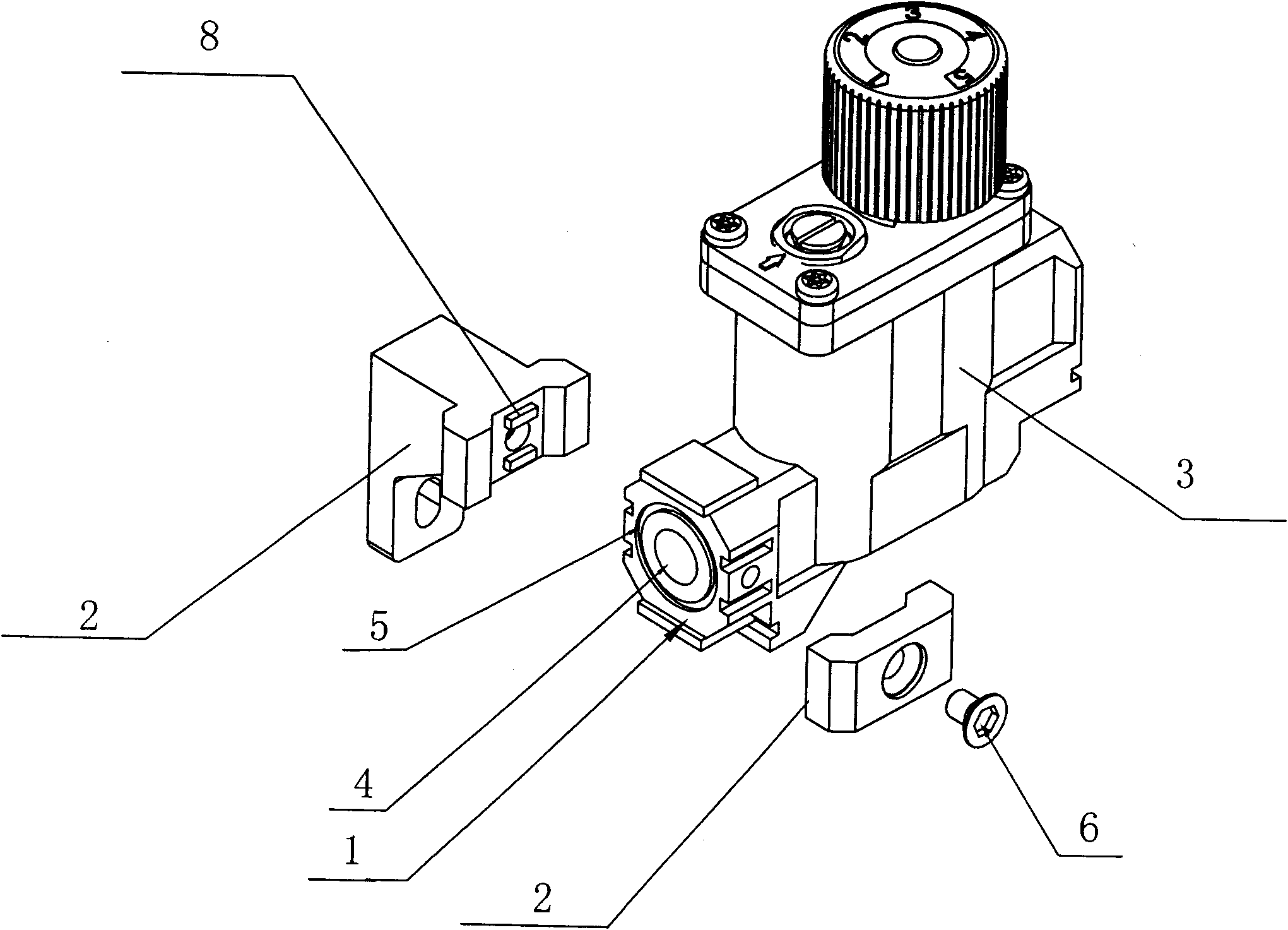
[0030] Such as figure 2 shown.

[0031] The difference between the present embodiment and the first embodiment is that the connecting piece 1 is directly fixed on the valve 3 to be connected. At this time, it is only necessary to install a sealing ring on the outer end surface of the connecting piece 1, and there is no need to process ring grooves 5 on both sides. During specific implementation, the two valves 3 that need to be connected can all have the connecting piece 1, and the span of the tightening part 2 should be made larger at this moment, or only one of the valves 3 has the connecting piece 1, and the Another valve 3 has the same structure as the first embodiment. The rest are all the same as in Example 1.


PUM


Abstract

The invention discloses a quick valve connecting device for gas-fired equipment, which is characterized by comprising a connecting piece (1) and a fastening piece (2); the connecting piece (1) is positioned between air inlets or air outlets corresponding to two valves (3) to be connected; the connecting piece (1) is provided with a through hole (4) communicating the air inlets or air outlets between the two valves (3) to be connected; two end faces of the connecting piece (1), opposite to the air inlets or the air outlets of the valves (3) to be connected, are all provided with a ring groove (5) for accommodating a sealing ring; two sides of the fastening piece (2) are lapped in the air inlets or air outlets of the valves (3); and the middle part of the fastening piece (2) is connected with the connecting piece (1) through a screw or bolt (6). The quick valve connecting device has the advantages of quick and convenient connection, small volume, and safety and reliability.

Description

technical field [0001] The invention relates to a gas equipment, in particular to a connection device commonly used in the gas equipment to connect gas paths between control valves, in particular to a quick valve connection device for the gas equipment. Background technique [0002] As we all know, there are many kinds of control valves in gas equipment (such as gas heaters), and the valves need to be connected. The traditional connection method is through pipes and pipe joints. However, due to the small size of gas equipment, the installation space is also very small. Small size, so it is very difficult to assemble. At the same time, due to the small operating space, it often affects the reliability of the connection, resulting in an unstable connection, causing gas leakage during use, and causing great hidden dangers to safe use. Therefore, designers often have to consider installation factors when designing, resulting in increased volume and cost of gas equipment. Conte...

Claims


Application Information

Patent Timeline
Patent Type & Authority Applications(China)
IPC IPC(8): F24D19/10
Inventor 罗伯特·泰勒占义兵
Owner PROCOM ELECTRIC APPLIANCES SHANGHAI
Why Eureka
Try Eureka