
Semi-module test box for dynamic compaction reinforced foundation model test

A technology of foundation model and model box, which is applied in the field of geotechnical engineering, can solve the problems that restrict the development and improvement of dynamic compaction method, the difficulty of indoor model test of dynamic compaction method, and the lack of theoretical basis.

Inactive Publication Date: 2010-09-15
TONGJI UNIV
View PDF4 Cites 17 Cited by
  • Summary
  • Abstract
  • Description
  • Claims
  • Application Information

AI Technical Summary

Problems solved by technology

However, there are still few studies on the reinforcement mechanism of dynamic compaction and the influence of various tamping parameters on the effect of dynamic compaction.
Although the dynamic compaction method has developed rapidly, the design and construction of the dynamic compaction method are still in a semi-theoretical and semi-empirical state, and the construction parameters on site still need to be determined through a large number of field tests, lacking the necessary theoretical basis, and there are large blindness and Uncertainty
Through the indoor model test, the reinforcement mechanism of the dynamic compaction method can be studied in depth, and the optimal design method of the dynamic compaction method can be proposed. However, due to the lack of a reasonable dynamic compaction indoor model test device, it is difficult to carry out the indoor model test of the dynamic compaction method, which restricts the dynamic compaction method. Further development and improvement of the law

Method used


Image

  • Semi-module test box for dynamic compaction reinforced foundation model test
  • Semi-module test box for dynamic compaction reinforced foundation model test
  • Semi-module test box for dynamic compaction reinforced foundation model test

Examples


Embodiment 1

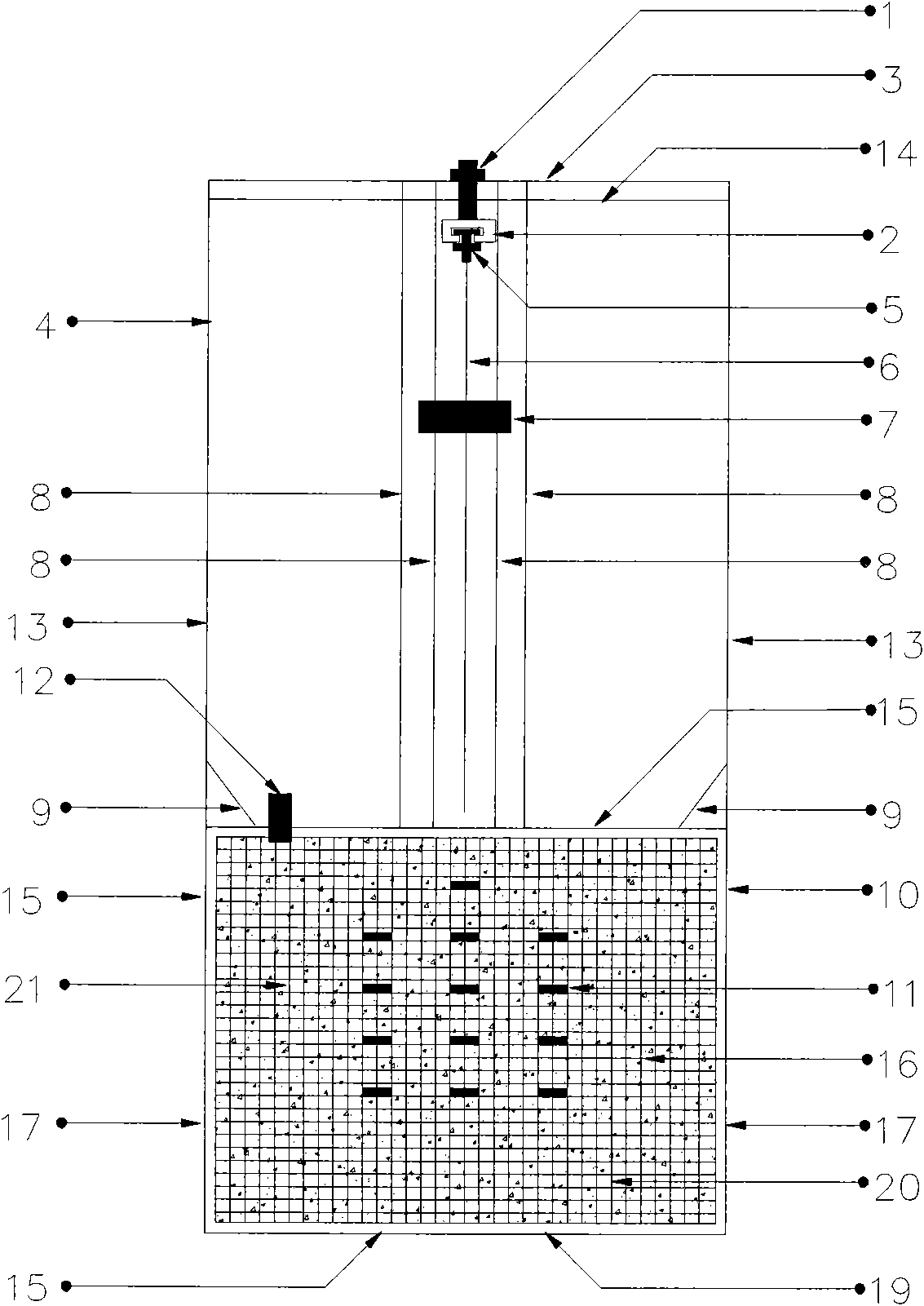
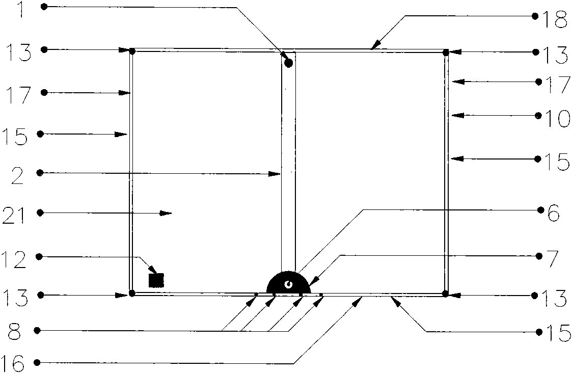
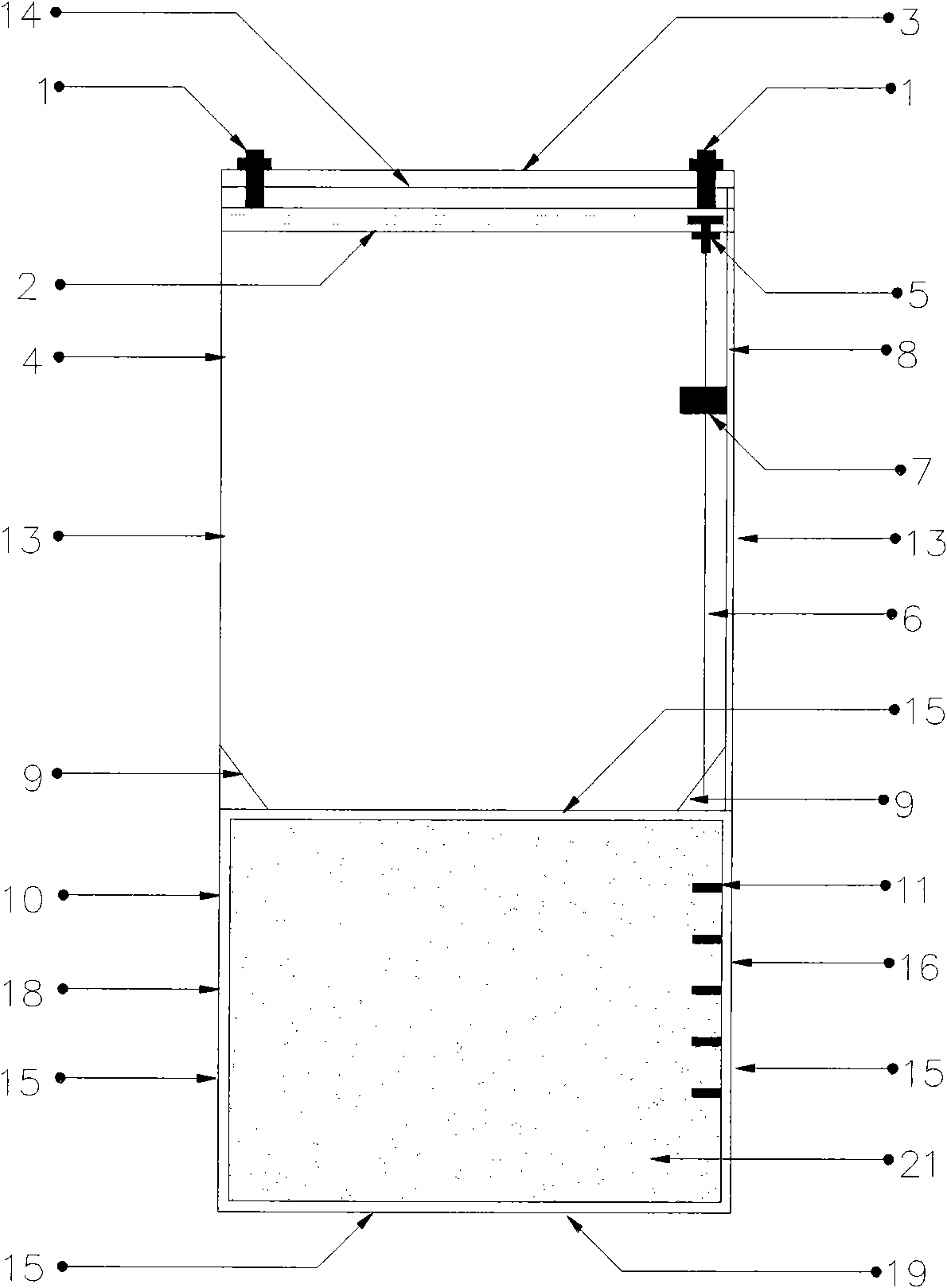
[0019] Embodiment 1, the length of the angle steel 15 in the model box 10 is 1000 mm, the width is 25 mm, and the thickness is 4 mm. The side panel 17 of model box 10, back panel 18 and base plate 19 are the planks of thickness 30 millimeters, and the front of model box 10 is the plexiglass plate 16 of thickness 10 millimeters, and the length and the width of each panel, base plate are 1000 millimeters, The surroundings of the model box frame are embedded in the angle steel 15, and are connected with the angle steel 15 by bolts. Graduation lines 20 are drawn on the plexiglass plate 16, and each grid size of the graduation lines is 10 mm×10 mm. Support 4 is welded by 4 vertical bars 13 and 4 cross bars 14, and vertical bars 13 and cross bars 14 are all 1000 millimeters in length, 20 millimeters in outer diameter, the steel pipe of wall thickness 2 millimeters. The four vertical rods 13 in the bracket 4 are located above the model box 10, connected with the angle steel 15 posit...


PUM


Abstract

The invention belongs to the technical field of rock-soil engineering, and in particular relates to a semi-module test box for dynamic compaction reinforced foundation model test. The semi-module test box consists of a chute, a fixed cross beam, a bracket, a guide rod, a semicircular model hammer, a limit rod, a fixed corner bracket, a model box, a soil pressure box and an acceleration sensor. The fixed cross beam is welded with a cross rod; and a vertical rod in the bracket is connected with an angle steel above the model box. The chute is fixed on the cross beam; a sliding bolt is embedded into the chute, the upper end of the guide rod is connected with the sliding bolt, and the lower end of the guide rod is suspended; and the guide rod passes through a central hole of the semicircular model hammer, the limit rod is positioned above the model box, the upper end of the limit rod is welded with the cross rod in the bracket, and the lower end of the limit rod is welded with the angle steel on the model box. The model box consists of the angle steel, an organic glass board, side panels, a back board and a bottom board; the soil pressure box is embedded in a soil sample; and the acceleration sensor is placed on the top of the soil sample. The semi-module test box ensures that the internal deformation of the soil under the action of dynamic compaction can be directly and conveniently observed, and can measure related data of dynamic stress and the like.

Description

technical field [0001] The invention belongs to the technical field of geotechnical engineering, and in particular relates to a half-mold test box for foundation model tests reinforced by a dynamic compaction method. Background technique [0002] The dynamic compaction method is a ground reinforcement method pioneered by the French Menard technology company in 1969. The soil is rammed with a rammer to make the soil more compact, and the strength and bearing capacity of the soil are greatly improved. In recent years, the dynamic compaction method has been widely used in foundation treatment projects at home and abroad, and has become one of the main methods for large-area foundation treatment. However, there are still few studies on the reinforcement mechanism of dynamic compaction and the influence of various tamping parameters on the effect of dynamic compaction. Although the dynamic compaction method has developed rapidly, the design and construction of the dynamic compac...

Claims


Application Information

Patent Timeline
IPC IPC(8): G01N33/24G01B5/30G01L1/00E02D33/00
Inventor 冯世进胡斌熊巨华高丽亚李夕林
Owner TONGJI UNIV
Learn More