Wide-band electric small-size directional coupler

A technology of directional coupler and electrically small size, which is applied in the direction of circuits, electrical components, waveguide devices, etc., can solve the problems of small space occupation, large space occupation, small size, etc., and achieve convenient implementation, compact structure, and small volume Effect

Active Publication Date: 2010-09-15
SUNWAVE COMM
View PDF5 Cites 13 Cited by
  • Summary
  • Abstract
  • Description
  • Claims
  • Application Information

AI Technical Summary

Problems solved by technology

However, due to its long length, it takes up a lot of space and is inconvenient to use
[0004] The structure of the second directional coupler is as figure 1 As shown, it includes a main transmission line 1 for transmitting radio frequency power and a coupling probe 2 composed of a coupling line. The coupling probe is placed in the energy distribution field of the main transmission line, and the two ends of the coupling line are bent to form a forward coupling output port. 21 and reverse coupling output port 22, also comprise the absorbing load 3 that links to each other with described reverse coupling output port; The advantage of this directional coupler is that size is little, takes up less space; But because coupling line is short, it is difficult to realize greater than Coupling degree above -15dB; within an octave, the coupling degree changes up to 6dB, if the frequency is unknown, the exact coupling degree cannot be obtained
This method can expand the frequency band of the coupler, but the disadvantage is that it needs software cooperation, and the working frequency must be known in advance, which limits its application range

Method used


Image

  • Wide-band electric small-size directional coupler
  • Wide-band electric small-size directional coupler
  • Wide-band electric small-size directional coupler

Examples


Embodiment Construction

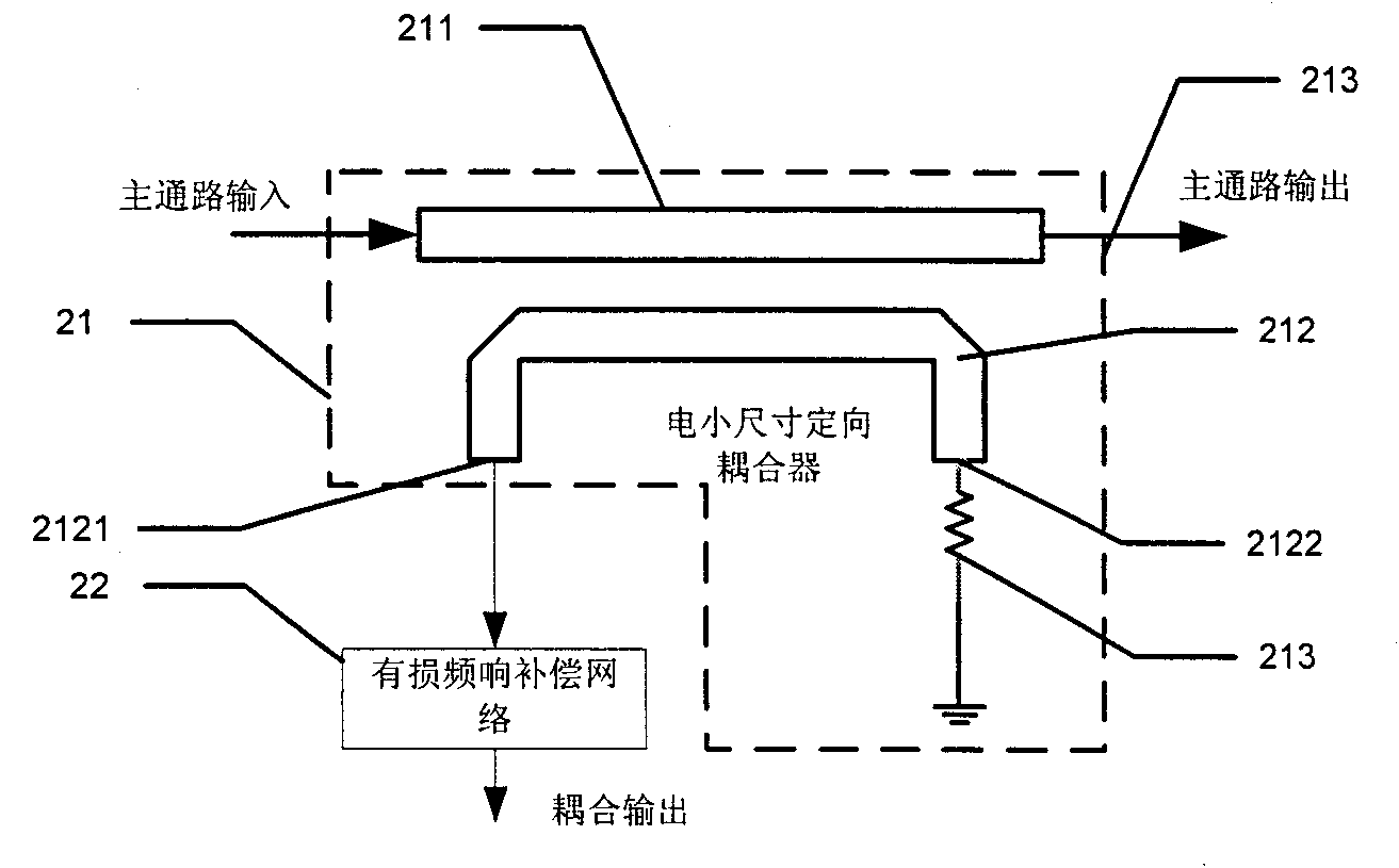
[0022] The broadband radio frequency electric small size directional coupler designed by the present invention is described in detail as follows in conjunction with the accompanying drawings and embodiments:

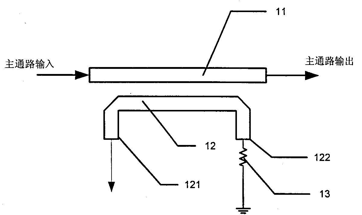
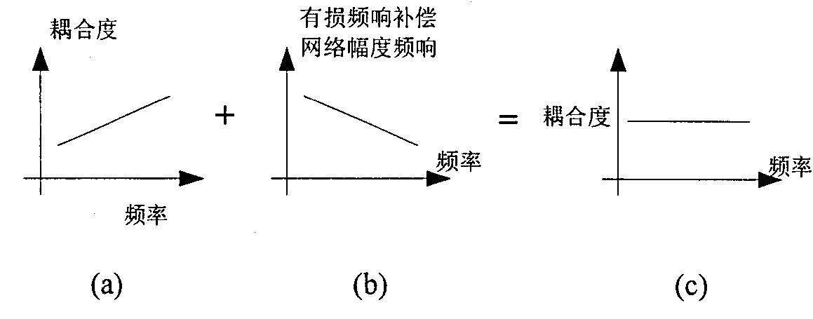
[0023] A broadband electric small size directional coupler designed by the present invention, such as figure 2 shown, including a narrow-band small size coupler 21, such as figure 2 In the middle dashed line frame, the narrow-band electric small-size coupler 21 includes a main transmission line 211 for transmitting radio frequency power and a coupling probe 212 composed of a coupling line. The coupling probe is placed in the energy distribution field of the main transmission line. Both ends are bent to form a forward coupling output port 2121 and a reverse coupling output port 2122, and the absorbing load 213 connected to the reverse coupling output port is characterized in that it also includes a lossy frequency response compensation network 22, the The input end of ...


PUM


Abstract

The invention relates to a wide-band electric small-size directional coupler, and belongs to the technical field of radio-frequency circuits. The directional coupler comprises a narrow-band electric small-size coupler, wherein the narrow-band electric small-size coupler comprises a section of main transmission line for transmitting radio-frequency power and a section of coupling probe consisting of a coupling line; the coupling probe is arranged in an energy distribution field of the main transmission line; both ends of the coupling line are bent to form a forward coupling output port and a back-coupling output port; and the narrow-band electric small-size coupler also comprises an absorbing load connected with the back-coupling output port. The wide-band electric small-size directional coupler is characterized by also comprising a lossy frequency response compensating network; the input end of the lossy frequency response compensating network is connected to the forward coupling output end of the narrow-band electric small-size directional coupler; and the output end of the lossy frequency response compensating network is used as the forward coupling output end of the wide-band electric small-size directional coupler. The wide-band electric small-size directional coupler has the characteristics of small volume, compact structure and convenient realization.

Description

technical field [0001] The invention belongs to the technical field of radio frequency circuits, and particularly relates to an improved design of a directional coupler with an electrically small size. Background technique [0002] The directional couplers currently used in radio frequency circuits have two size characteristics: one is a quarter wavelength or more in length; the other is less than a tenth of a wavelength in length. [0003] The advantage of the first directional coupler is that it is easy to achieve a strong coupling degree, and the frequency response fluctuation of the coupling degree is relatively small, typically, the flatness in one octave is better than ±0.5dB. However, due to its long length and large space occupation, it is inconvenient to use. [0004] The structure of the second directional coupler is as follows figure 1 As shown, it includes a main transmission line 1 for transmitting radio frequency power and a coupling probe 2 composed of a cou...

Claims


Application Information

Patent Timeline
Patent Type & Authority Applications(China)
IPC IPC(8): H01P5/18
Inventor 刘宁蔡晓亚
Owner SUNWAVE COMM
Why Eureka
Try Eureka