Overvoltage protection circuit for integrated circuit
An overvoltage protection circuit and integrated circuit technology, applied in emergency protection circuit devices, emergency protection circuit devices for limiting overcurrent/overvoltage, circuit devices, etc., can solve the problem of increasing system complexity, failing to meet energy conservation and environmental protection, Problems such as large power consumption, to achieve the effect of reducing complexity, easy overvoltage protection, and a wide range of applications
- Summary
- Abstract
- Description
- Claims
- Application Information
AI Technical Summary
Problems solved by technology
Method used
Image
Examples
Embodiment 1
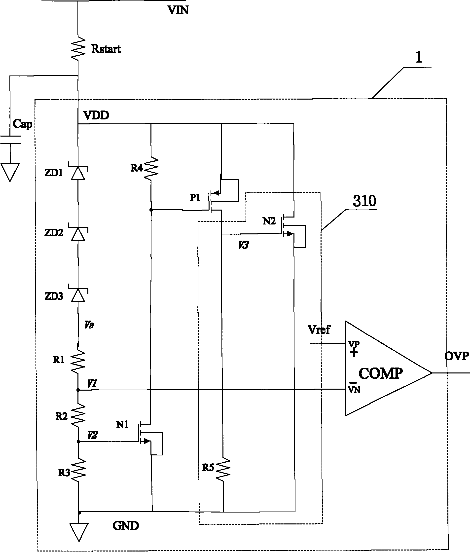
[0024] Such as Figure 3aAs shown, an integrated circuit overvoltage protection circuit 1 includes a first resistor R1, a second resistor R2, a third resistor R3, a fourth resistor R4, a fifth resistor R5, a PMOS transistor P1, a first NMOS transistor N1, A second NMOS transistor N2, a comparator COMP and three Zener diodes. The three Zener diodes are connected in turn, the cathode of the first Zener diode ZD1 is connected to the input power supply VDD. , the anode of the first Zener diode ZD1 is connected to the cathode of the second Zener diode ZD2, the anode of the second Zener diode ZD2 is connected to the cathode of the third Zener diode ZD3, and the anode of the third Zener diode ZD3 is connected to the cathode of the third Zener diode ZD3 The first end of the first resistor R1 is connected, the second end of the first resistor R1 is connected to the first end of the second resistor R2, and the second end of the first resistor R1 is connected to the first end of the sec...
Embodiment 2
[0038] The circuit structure of this embodiment is basically the same as that of Embodiment 1, the only difference is that the number of Zener diodes included in this embodiment is four, such as Figure 3b As shown, they are the first Zener diode ZD1, the second Zener diode ZD2, the third Zener diode ZD3 and the fourth Zener diode ZD4. The cathode of the first Zener diode ZD1 is connected to the input power supply, and the first Zener diode The anode of ZD1 is connected to the cathode of the second Zener diode ZD2, the anode of the second Zener diode ZD2 is connected to the cathode of the third Zener diode ZD3, and the anode of the third Zener diode ZD3 is connected to the cathode of the fourth Zener diode ZD4 The cathode of the fourth zener diode ZD4 is connected to the first terminal of the first resistor R1.
Embodiment 3
[0040] The circuit structure of this embodiment is basically the same as that of Embodiment 1 and Embodiment 2, the difference is that only one Zener diode ZD1 is included in this embodiment, such as Figure 3c As shown, the cathode of the Zener diode ZD1 is connected to the input power supply, and the anode of the Zener diode ZD1 is connected to the first end of the first resistor R1.
[0041] In fact, in the actual design process, the number of zener diodes is not limited to the number exemplified in the three embodiments of the present invention, and the threshold of overvoltage protection can be controlled by adjusting the number of zener diodes, such as Figure 3b , the overvoltage protection threshold can be increased by adding a zener diode, while Figure 3c Among them, the overvoltage protection threshold is lowered by reducing two Zener diodes.
PUM
 Abstract
Description
Claims
Application Information
 - R&D
- Intellectual Property
- Life Sciences
- Materials
- Tech Scout
- Unparalleled Data Quality
- Higher Quality Content
- 60% Fewer Hallucinations
Browse by: Latest US Patents, China's latest patents, Technical Efficacy Thesaurus, Application Domain, Technology Topic, Popular Technical Reports.
© 2025 PatSnap. All rights reserved.Legal|Privacy policy|Modern Slavery Act Transparency Statement|Sitemap|About US| Contact US: help@patsnap.com


