
Weft knitting machine, and method for detecting abnormal vibrations in the weft knitting machine

A vibration detection and flat knitting technology, applied in textile and papermaking, weft knitting, knitting, etc., can solve the problem of difficulty in detecting abnormal vibration, and achieve the effect of preventing detection omission and avoiding detection omission.

Active Publication Date: 2010-09-15
SHIMA SEIKI MFG LTD
View PDF2 Cites 6 Cited by
  • Summary
  • Abstract
  • Description
  • Claims
  • Application Information

AI Technical Summary

Problems solved by technology

As a result, the difference between the abnormal lateral vibration caused by the abnormal contact between the carriage and the knitting needle and the lateral vibration caused by normal knitting becomes small, and it may be difficult to distinguish the two and detect abnormal vibration with high sensitivity.

Method used


Image

  • Weft knitting machine, and method for detecting abnormal vibrations in the weft knitting machine
  • Weft knitting machine, and method for detecting abnormal vibrations in the weft knitting machine
  • Weft knitting machine, and method for detecting abnormal vibrations in the weft knitting machine

Examples


Embodiment approach 1

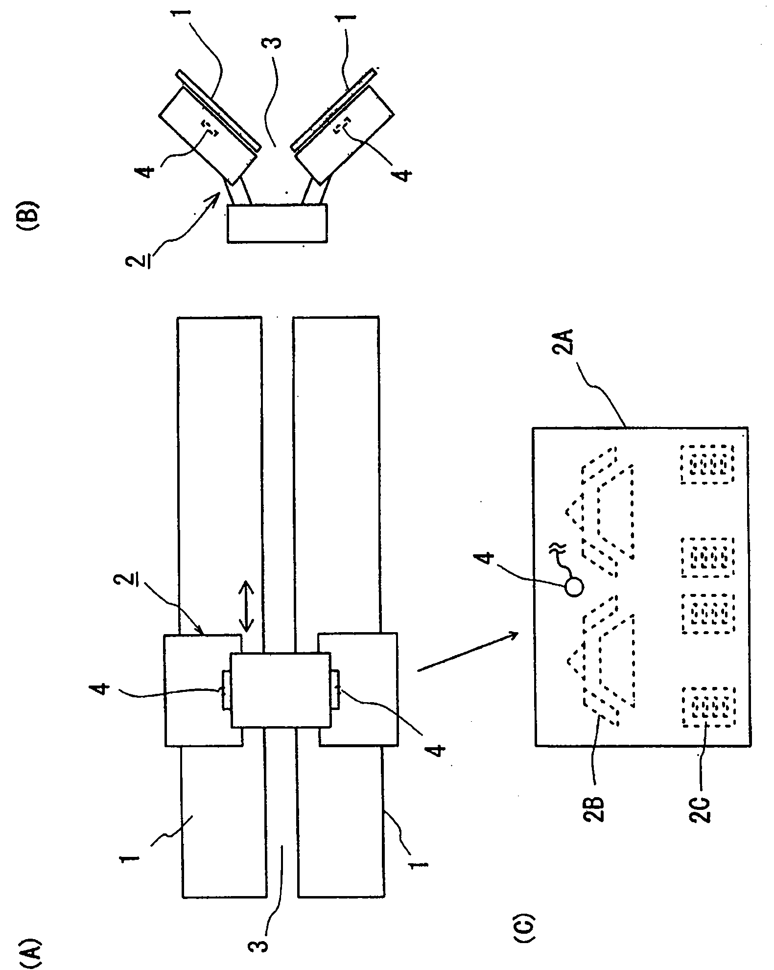
[0037] figure 1 The needle bed 1 and the carriage 2 of the flat knitting machine of the present invention are schematically shown. Here, a so-called two-needle-bed flat knitting machine, that is, a flat knitting machine having a pair of needle beds 1 extending in the left-right direction and facing each other in the front-rear direction, will be described as an example. The structures of the needle bed 1 (knitting needles) and the carriage 2 are basically the same as known structures. That is, many knitting needles (not shown) on the needle bed 1 are arranged in the left-right direction and accommodated in the needle grooves. The carriage 2 has a structure in which a pair of cam plates 2A arranged to cover a part of the front and rear needle beds 1 are connected above the needle bed 3, and can reciprocate on the needle beds 1 in the left-right direction. The cam plate 2A is provided with a knitting cam 2B and a needle selection cam 2C. When the cam carriage 2 reciprocates, ...

Embodiment approach 2

[0053] Next, according to Figure 5 An embodiment will be described in which only abnormal vibrations can be detected even when vibrations caused by normal knitting operations are shocking and relatively large orthogonal vibrations. This embodiment differs from Embodiment 1 only in that detection control unit 7 is provided, and other configurations are the same as Embodiment 1, so the difference will be mainly described below.

[0054] The detection control unit 7 provided in the present embodiment extracts the vibration caused by the normal knitting operation as a non-detection interval which is impact and large orthogonal vibration, and invalidates the vibration detection by the vibration detection sensor 4 in the non-detection interval. This so-called "vibration detection is invalidated" includes any of the following situations: (1) the situation where the vibration detection sensor 4 is stopped and does not carry out vibration detection itself; The case of abnormality jud...


PUM


Abstract

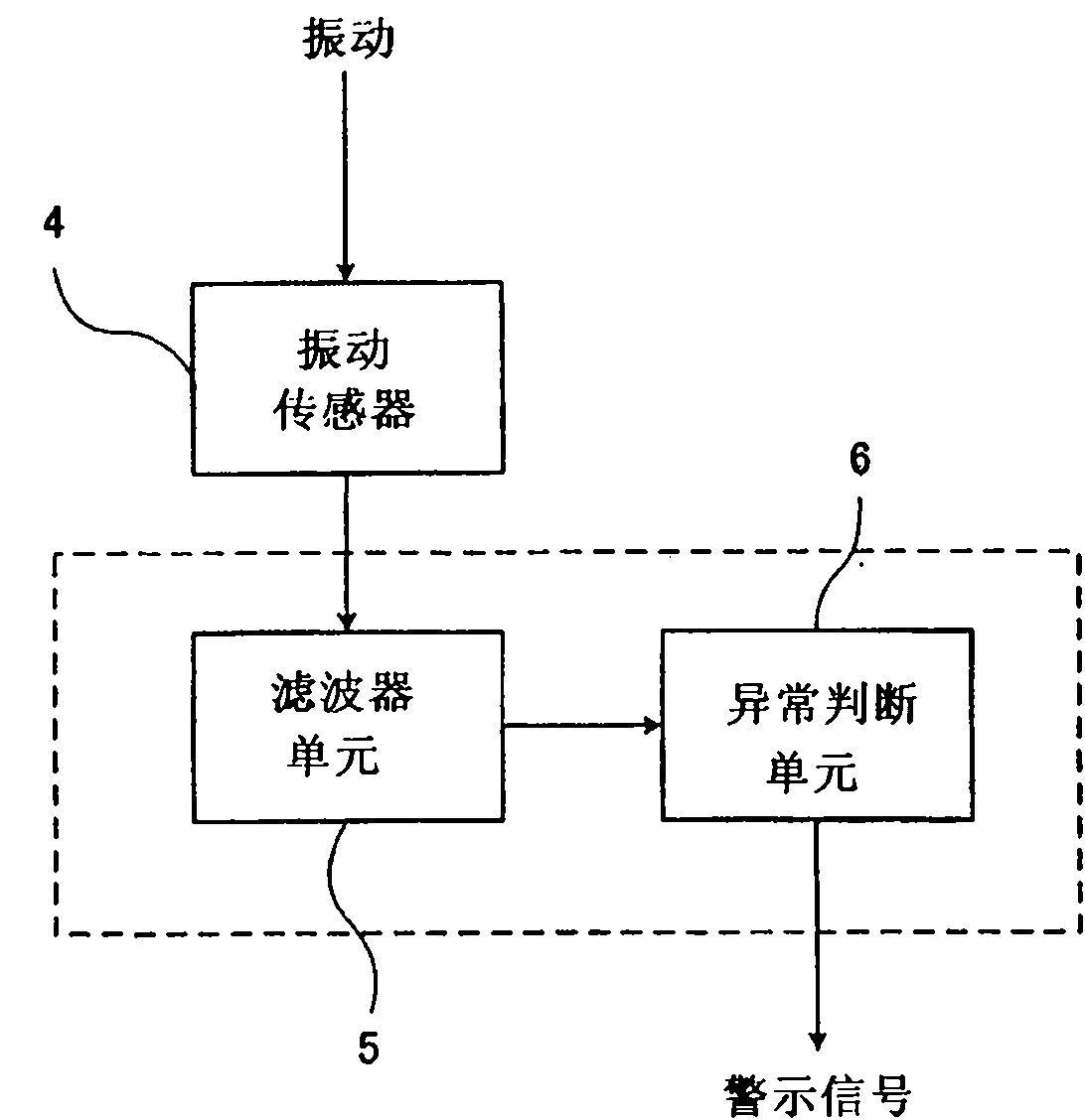
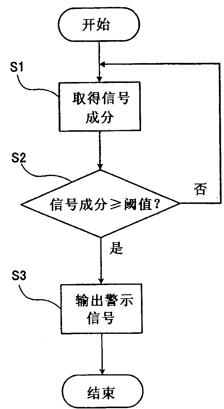
A weft knitting machine can detect abnormal vibrations resulting from an abnormal contact between a carriage and knitting needles, in a high sensitivity. A method can detect those abnormal vibrations. The weft knitting machine comprises a needle bed (1) having a plurality of knitting needles arrayed in parallel, and a carriage (2) running reciprocally over the needle bed (1) for moving the knitting needles back and forth. The carriage (2) includes vibration detecting means (or a vibration sensor (4)), which detects the vibrations to occur in a direction to intersect the running direction of the carriage (2). On the basis of the detection result, abnormal deciding means decides whether or not the abnormal vibrations are caused by the abnormal contact between the carriage (2) and the knitting needles. Even in case the running speed of the carriage (2) is high, the abnormal vibrations can be so detected as are discriminated from the vibrations accompanying the normal knitting operation.

Description

technical field [0001] The invention relates to a flat knitting machine and a method for detecting abnormal vibration in the flat knitting machine. Background technique [0002] Conventionally, a flat knitting machine is known that includes a needle bed on which a plurality of knitting needles are arranged, and a carriage that moves the knitting needles forward and backward by reciprocating on the needle bed. The knitting needle includes a needle body having a hook at the tip, a needle jack, a needle selector jack, and a needle selector, and these components are sequentially engaged with each other and housed in the needle grooves of the needle bed. In addition, the jacks, selector jacks, and selector jacks have butts protruding from the needle grooves. On the other hand, the carriage includes a knitting cam engaged with each butt of the needle jack and the selector jack, and a selector cam engaged with the butt of the selector jack. Then, by causing the carriage to recipr...

Claims


Application Information

Patent Timeline
Patent Type & Authority Applications(China)
IPC IPC(8): D04B35/18D04B15/96
CPCD04B35/18D04B15/96
Inventor 南方胜次森淳中山泰宏
Owner SHIMA SEIKI MFG LTD
Learn More