Damper and door handle with the same
A technology of air damping and cylinder, applied in the field of door handle and damper
- Summary
- Abstract
- Description
- Claims
- Application Information
AI Technical Summary
Problems solved by technology
Method used
Image

Examples
no. 1 approach
[0079] Next, the air damper according to the first embodiment of the present invention will be described.
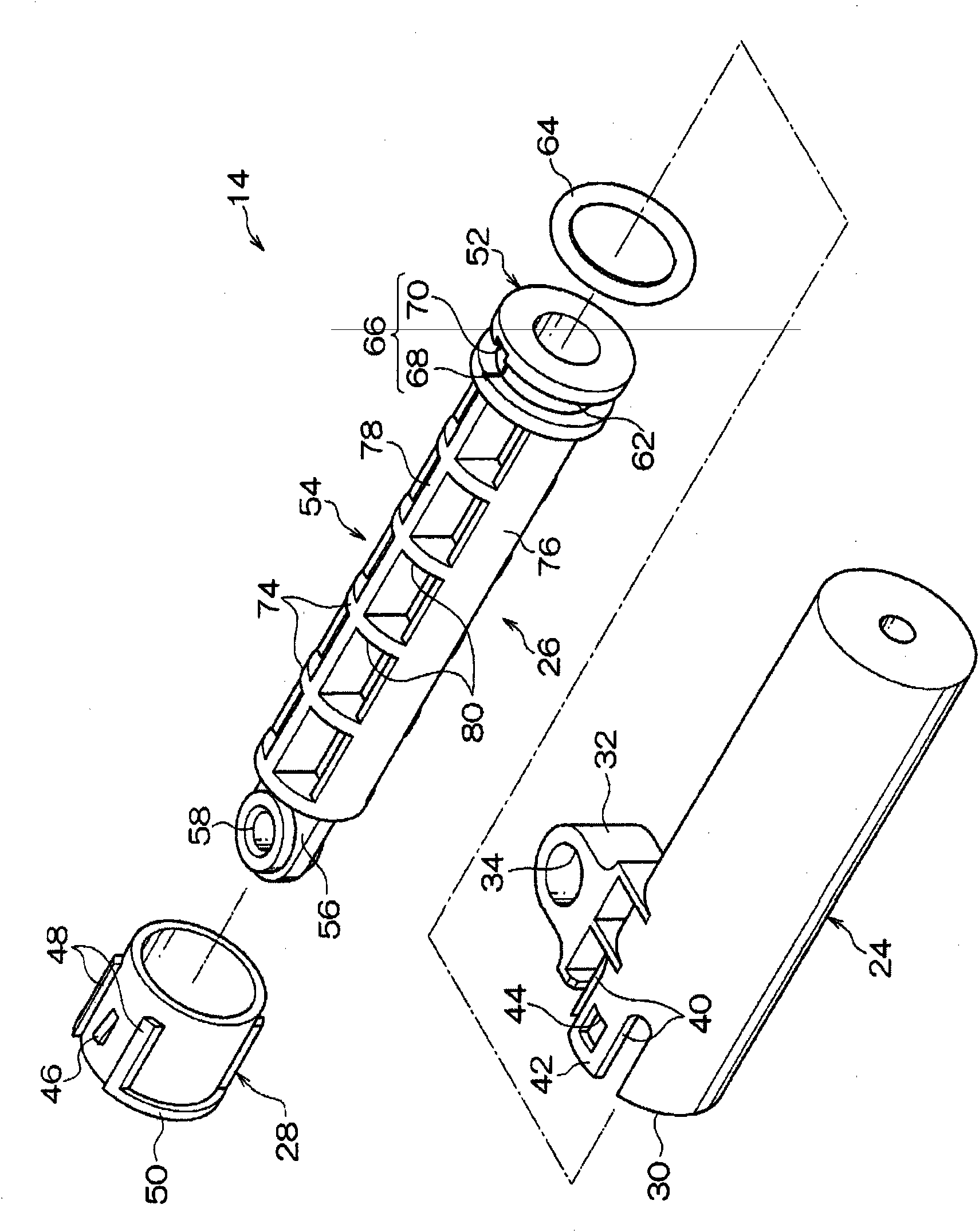
[0080] like image 3 As shown, the air damper 14 is roughly divided into a cylinder 24 , a piston member 26 and a sleeve 28 , and the piston member 26 accommodated in the cylinder 24 is prevented from falling off by the sleeve 28 .
[0081] cylinder
[0082] First, the cylinder 24 will be described. like figure 2 and image 3 As shown, the cylinder 24 is formed in a bottomed cylindrical shape, and an opening 30 is provided at one end. On the side of the opening 30 of the cylinder 24, a connecting piece (first connecting mechanism) 32 that protrudes from the outer peripheral surface of the cylinder 24 is provided.
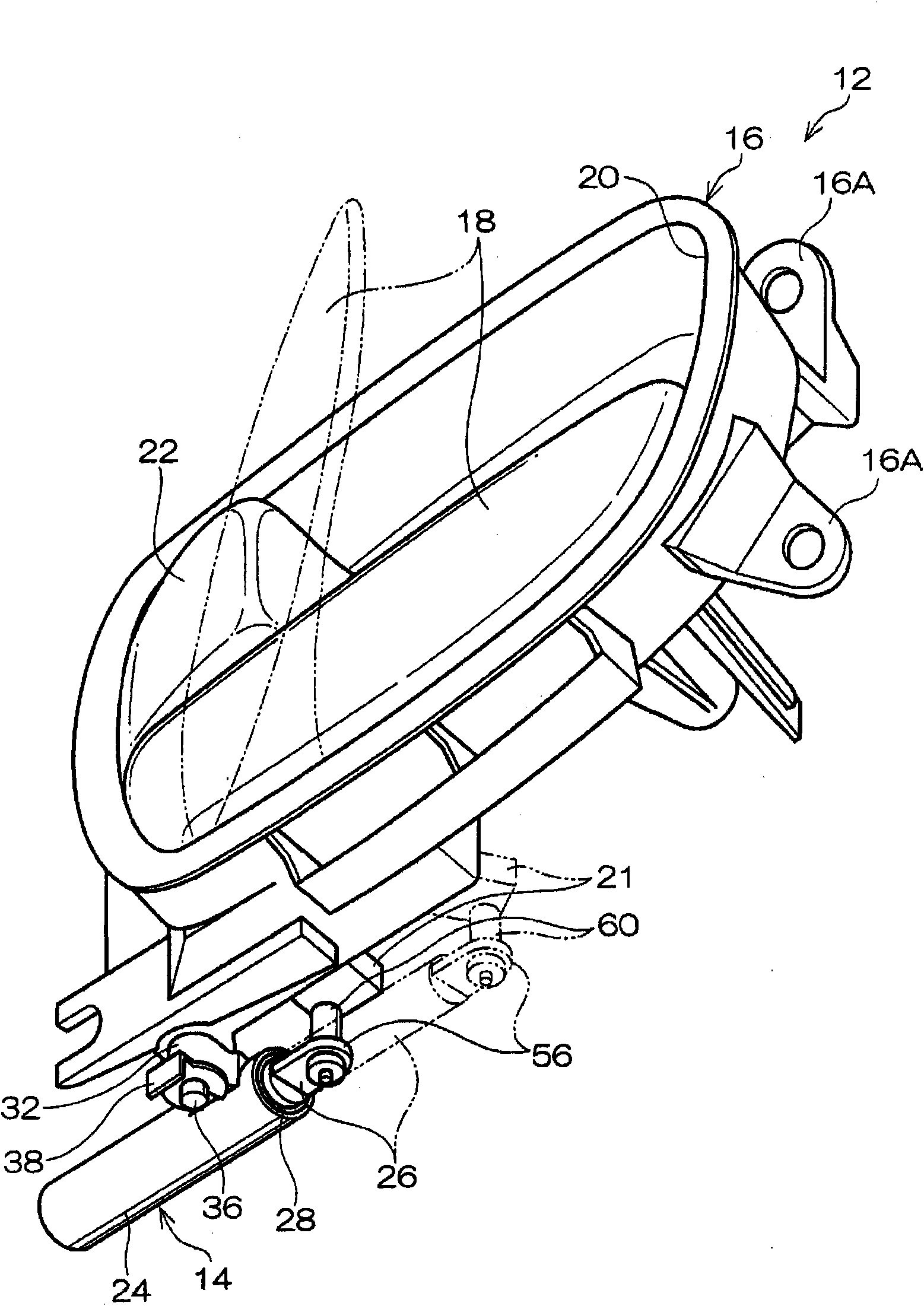
[0083]A connecting hole (first connecting mechanism) 34 is formed in the central portion of the connecting piece 32 . The shaft portion (first connecting mechanism) 36 provided on the lower surface side of the main body portion 16 can be inserted throug...
no. 2 approach
[0118] Next, an air damper according to a second embodiment of the present invention will be described. In addition, the content substantially the same as that of the first embodiment will not be briefly described.
[0119] like Figure 7 As shown, a plurality of substantially prismatic through-holes 94 penetrating in a direction perpendicular to the axial direction of the cylindrical piston rod 92 are provided. Thereby, the wall thickness of the piston rod 92 can be made substantially uniform, the shrinkage cavity of the outer peripheral wall of the piston rod 92 can be suppressed, and the precision of the outer diameter dimension of the piston rod 92 can be improved. In addition, although not shown, a hollow portion may be provided in the axial direction of the piston rod.
no. 3 approach
[0121] Next, an air damper according to a third embodiment of the present invention will be described. In addition, descriptions of substantially the same contents as those of the first embodiment will be omitted.
[0122] In the first embodiment, the sleeve 28 is inserted into the opening 30 of the cylinder 24, and as Figure 8 As shown, if the outer diameters of the piston 100 and the piston rod 102 are the same, the pipe sleeve may not be required. Since the opening and closing angle of the operating rod 18 is regulated, the stroke of the piston 100 is also regulated, and the piston 100 will not come off from the cylinder 104 even if there is no sleeve.
[0123] Also, at this time, the gap between the outer peripheral wall of the piston rod 102 and the inner peripheral wall of the cylinder 104 is reduced. Here, since no sleeve is used, as Figure 5A As shown, it is not necessary to make the distance between the disc portion 74 of the piston rod 54 below the depth (H) of ...
PUM
 Abstract
Description
Claims
Application Information
 - R&D
- Intellectual Property
- Life Sciences
- Materials
- Tech Scout
- Unparalleled Data Quality
- Higher Quality Content
- 60% Fewer Hallucinations
Browse by: Latest US Patents, China's latest patents, Technical Efficacy Thesaurus, Application Domain, Technology Topic, Popular Technical Reports.
© 2025 PatSnap. All rights reserved.Legal|Privacy policy|Modern Slavery Act Transparency Statement|Sitemap|About US| Contact US: help@patsnap.com