Fluid stirring paddle

A technology of fluid stirring and paddle arm, which is applied in the direction of mixers, dissolvers, and mixers with rotating stirring devices. It can solve the problems of affecting the mixing effect, clumping phenomenon, easy to generate negative pressure, etc., and achieve superior mixing effect and material circulation. Smooth, blending effect

Inactive Publication Date: 2010-09-22
钟荣华
View PDF5 Cites 10 Cited by
  • Summary
  • Abstract
  • Description
  • Claims
  • Application Information

AI Technical Summary

Problems solved by technology

The operation defect of this agitator is: (1), because the upper part of two torsion helicoids is connected by oblique connection arm, and between two oblique connection arms, be cone-shaped, make in the course of work, the agitator of this agitator It is easy to accumulate material in the conical middle frame, which is the "grouping phenomenon" in the industry; (2) During the working process, negative pressure is easy to be generated behind the direction of movement of this kind of agitator, so that the material accumulates, which is the industry (3) Since the upper part of this kind of agitator is conical, when working, it is easy to cause the material to crawl upward along the outer wall of the torsion spiral of the agitator, which is what is called "crawling" in the industry. rod phenomenon"
Because existing agitators are prone to "grouping phenomenon", "agglomeration phenomenon" and "rod climbing phenomenon", and these three phenomena seriously affect the stirring effect, therefore, the existing agitator structure generally has poor stirring effect, Defects such as low working efficiency and difficulty in cleaning cannot fully realize the original purpose of the agitator to effectively agitate and mix industrial fluid materials

Method used


Image

  • Fluid stirring paddle
  • Fluid stirring paddle
  • Fluid stirring paddle

Examples


Embodiment 1

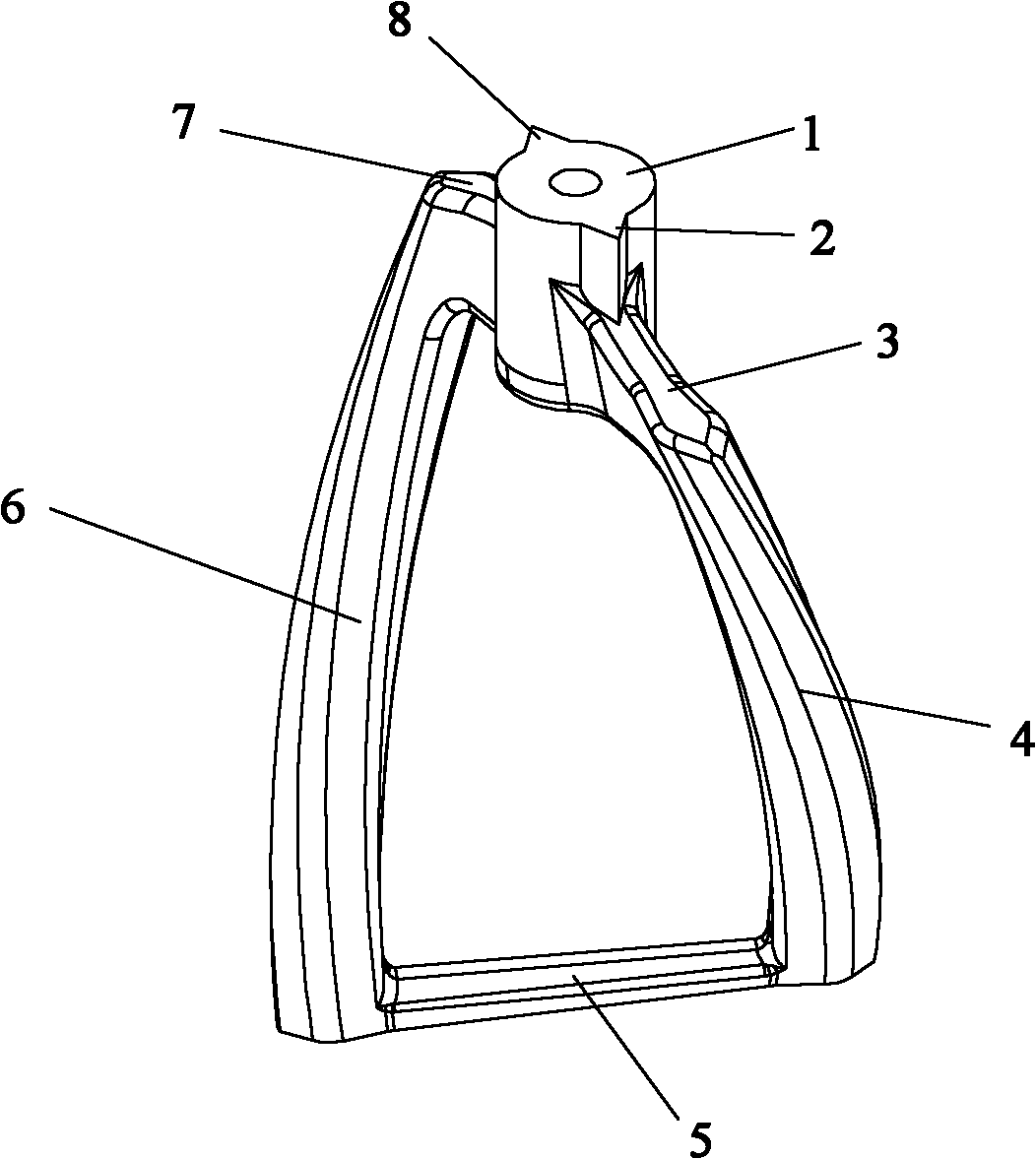
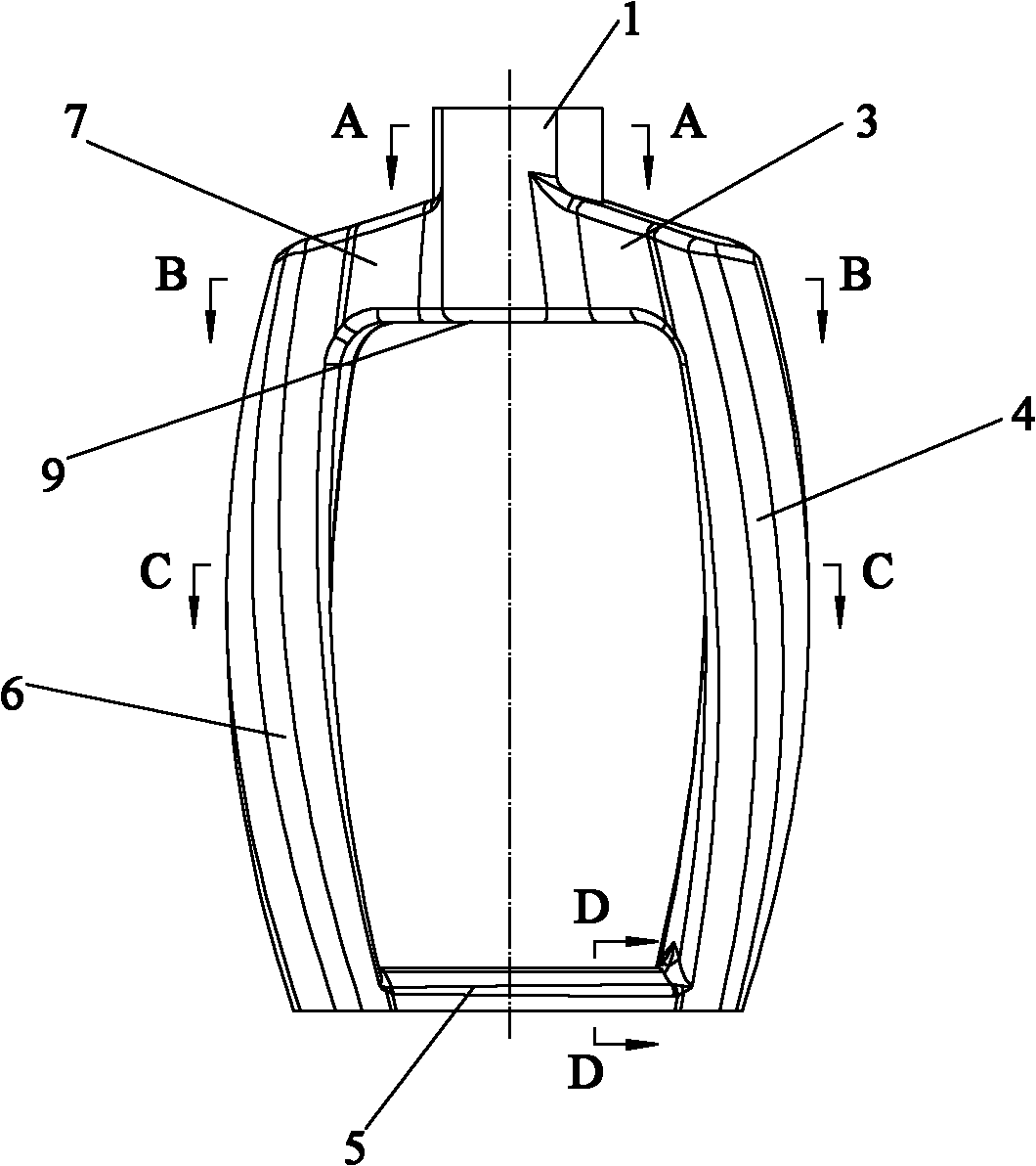
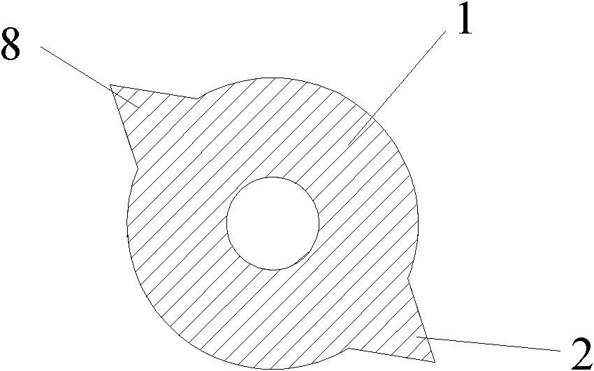
[0031] Figure 1 to Figure 8 Shows the specific structural schematic diagram of this embodiment, such as figure 1 As shown, the fluid stirring paddle includes a shaft head 1 for connecting with a rotating shaft, two helical paddle arms 4, 6, and a paddle bottom 5 connecting the bottoms of the two paddle arms; the left and right sides of the shaft head 1 are Outward extension forms two paddle shoulders 3,7, as Figure 4 Shown; The undersides of two paddle shoulders 3,7 are connected to form a horizontal plane 9, as figure 2 As shown; the two ends of the two paddle shoulders 3,7 extend downwards to form the two paddle arms 4,6, as figure 1 and Figure 8 shown.

[0032] like figure 2 As shown, the two paddle shoulders 3, 7 extend outward from the middle of the shaft head 1, and the heights of the two paddle shoulders 3, 7 gradually decrease from inside to outside.

[0033] like figure 1 As shown, the left and right sides of the upper part of the shaft head 1 extend outwa...

Embodiment 2

[0040] The structure of this embodiment is the same as that of Embodiment 1 except for the following features: the left and right sides of the upper part of the shaft head extend outward to form four columns with gradually decreasing thicknesses, two of which are arranged on the left side of the upper part of the shaft head, and the other two One is located on the right side of the upper part of the shaft head; the bottom of the column is connected with the top of the oar shoulder.

Embodiment 3

[0042] This embodiment has the same structure as Embodiment 1 except for the following features: the length of the paddle arm in the radial direction of the shaft head is 10 mm, and the length in the direction of rotation is 5 mm; the length of the shortest side in the cross section of the paddle arm is 1 mm.


PUM

PropertyMeasurementUnit
Lengthaaaaaaaaaa

Abstract

The invention provides a fluid stirring paddle. The stirring paddle comprises a spindle head, two helical paddle arms and a paddle bottom, wherein the spindle head is used for connecting a rotating shaft; the paddle bottom is connected with the bottoms of the two paddle arms; the left and right sides of the spindle head extend outwards to form two paddle shoulders; the lower lateral surfaces of the two paddle shoulders are connected to form a horizontal plane; the two ends of the paddle shoulders extend downwards to form the two paddle arms, the paddle shoulders extend outwards from the middle of the spindle head, and the heights of the two paddle shoulders are gradually reduced from inside to outside; the upper left and right sides of the spindle head extend outwards to form at least two upright posts with gradually-reduced thicknesses; the bottoms of the upright posts are connected with the tops of the paddle shoulders; the cross sections of the upright posts are triangular; and the cross section of the paddle bottom is in a shape of a semi circle of which the bottom is inclined to the rotation direction. The stirring paddle has the advantages of effectively avoiding the 'aggregation phenomenon', 'clustering phenomenon' and 'pole climbing phenomenon', ensuring the excellent stirring effect of materials upon stirring and mixing the materials and fully fulfilling the aim of effectively stirring and mixing industrial fluid materials.

Description

technical field [0001] The invention relates to a stirrer, in particular to a fluid stirring paddle used for stirring and mixing industrial fluid materials in chemical industry, energy, electronics, medicine and other industries. Background technique [0002] At present, in chemical industry, energy, electronics, medicine and other industries, planetary mixers used for stirring and mixing industrial fluid materials generally use symmetrically distributed agitators. The Chinese utility model patent with the application number "200820178225.6" discloses a planetary vacuum mixer. The agitator includes two twisted helicoids. The cross-section is an irregular hexagon, and the lower parts of the two twisted helices are connected by a connecting beam. The operation defect of this agitator is: (1), because the upper part of two torsion helicoids is connected by oblique connection arm, and between two oblique connection arms, be cone-shaped, make in the course of work, the agitator ...

Claims


Application Information

Patent Timeline
IPC IPC(8): B01F7/00B01F7/30
Inventor 钟荣华
Owner 钟荣华
Why Eureka
Try Eureka