Underground ultrasonic oil-production transducer with matching device

A technology of matching devices and transducers, which is applied to vibration generating devices, earthwork drilling, boreholes/well components, etc., can solve problems such as large reactive current, waste of resources, and low transmission efficiency of the transmission system, and reduce capacity Sexual impedance, energy saving, and the effect of improving transmission efficiency

Inactive Publication Date: 2010-09-22
HEILONGJIANG LANDE ULTRASONIC TECH CO LTD
View PDF4 Cites 4 Cited by
  • Summary
  • Abstract
  • Description
  • Claims
  • Application Information

AI Technical Summary

Problems solved by technology

[0003] In order to solve the problem that the existing piezoelectric ceramic transducer causes the entire transmission system to generate relatively large reactive current, the transmission efficiency of the transmission system is extremely low, and the problem of serious waste of resources, the present invention proposes a downhole ultrasonic oil stimulation with a matching device with transducer

Method used


Image

  • Underground ultrasonic oil-production transducer with matching device
  • Underground ultrasonic oil-production transducer with matching device

Examples


specific Embodiment approach 1

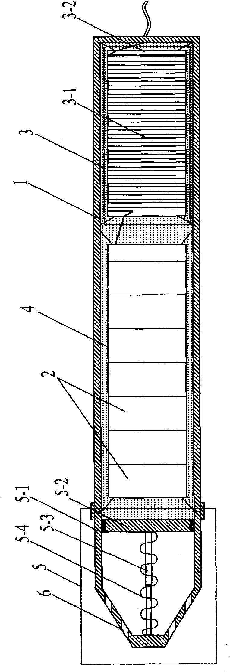
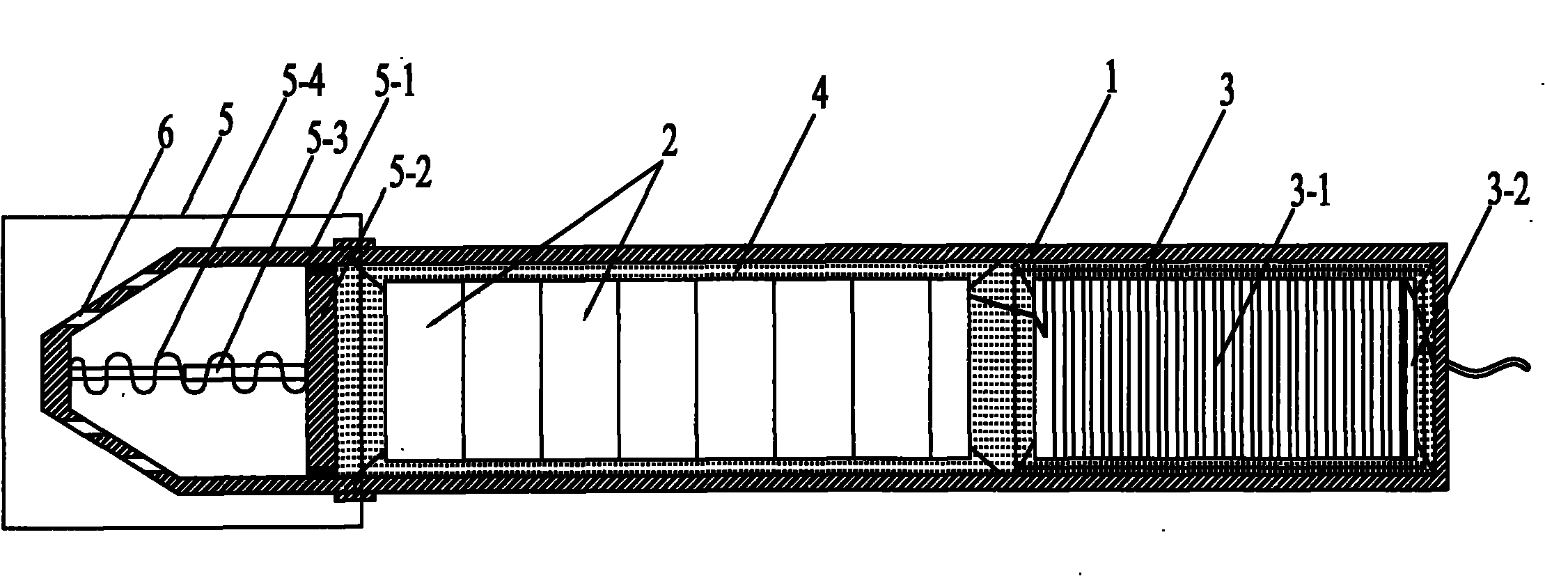
[0007] Specific implementation mode one: combine figure 1 Describe this embodiment, which consists of a cylindrical housing 1, multiple identical piezoelectric ceramic oscillating rings 2, two identical inductance matching devices 3, filling liquid 4, pressure balancing device 5 and two fixing frames; cylindrical The housing 1 is a bottomless metal cylinder; the plurality of identical piezoelectric ceramic oscillating rings 2 and two inductance matching devices 3 are installed inside the cylindrical housing 1, and the plurality of identical piezoelectric ceramic oscillating rings The rings 2 are tightly fixed on a fixed frame inside the cylindrical shell 1, and two identical inductance matching devices 3 are overlapped on another fixed frame inside the cylindrical shell 1; The fixing frame of the piezoelectric ceramic oscillating ring 2 is fixedly arranged at the bottom of the cylindrical housing 1, and the fixing frame with two identical inductance matching devices 3 is fixed...

specific Embodiment approach 2

[0010] Embodiment 2: This embodiment differs from Embodiment 1 in that the winding directions of the inductance coils 3 - 1 in the two inductance matching devices 3 are the same. Other compositions and connection methods are the same as those in Embodiment 1. Since the inductance matching device 3 is arranged inside the airtight cylindrical casing 1, and the cylindrical casing 1 is a bottomless metal cylinder, when the inductance matching device 3 is fed with a high-frequency electrical signal, it may be in the cylindrical casing. 1, the induced current is generated on the metal tube wall, which causes the partial voltage breakdown of the transducer and affects the reliability of the entire transmission system. The purpose of the same winding direction of the inductance coil 3-1 in the two inductance matching devices 3 is to make the magnetic field lines passing through the metal pipe wall of the cylindrical shell 1 can be enclosed in the coil, and basically eliminate the magn...

specific Embodiment approach 3

[0011] Embodiment 3: This embodiment differs from Embodiment 1 or Embodiment 2 in that the filling liquid 4 is made of silicone oil or transformer oil. Other compositions and connection modes are the same as those in Embodiment 1 or 2. The advantage of using silicone oil as the filling liquid 4 is that it has good insulation performance and good thermal conductivity.


PUM


Abstract

The invention relates to an underground ultrasonic oil-production transducer with a matching device, in particular to a transducer for solving the problems of extremely low transmission efficiency and serious resource waste of a traditional piezoelectric ceramic transducer transmission system. A fixing frame with a plurality of fixed identical piezoelectric ceramic oscillators is fixedly arranged at the bottom of a cylindrical shell, a fixing frame with two identical fixed inductor matching devices is fixedly arranged at the top of the cylindrical shell, an inductor coil is tightly wound on a hollow cylindrical inductor frame, two incoming terminals of an inductor coil of an inductor matching device hermetically penetrate through the top end surface of the cylindrical shell and are connected with external transmission cables, two outgoing terminals of the inductor coil of the inductor matching device are connected with two incoming terminals of an inductor coil of the other inductor matching device, and two outgoing terminals of the inductor coil of the other inductor matching device are connected in parallel with two terminals of each piezoelectric ceramic oscillator. The invention has the advantages of high transmission efficiency and energy saving.

Description

technical field [0001] The invention relates to a transducer, in particular to a transducer for downhole ultrasonic oil recovery. Background technique [0002] At present, ultrasonic oil stimulation technology is widely used in major oil fields. The working principle of its oil stimulation is to use the ultrasonic power source to transmit electric energy to the transducer installed in the downhole, and the transducer converts the received electric energy into Oscillating mechanical energy and transferring this oscillating mechanical energy to the oil in the surrounding rock crevices, reducing its viscosity, speeding up its flow, and facilitating oil pumping operations, so as to achieve the purpose of increasing oil. Now the general transducer mainly adopts the piezoelectric ceramic transducer, which will make the transmission system composed of the ultrasonic power source, the transmission cable and the piezoelectric ceramic transducer have a large The capacitive impedance ...

Claims


Application Information

Patent Timeline
Patent Type & Authority Applications(China)
IPC IPC(8): E21B28/00
Inventor 罗德坤李勇强申华楠赵树山杜文
Owner HEILONGJIANG LANDE ULTRASONIC TECH CO LTD
Why Eureka
Try Eureka