
Bearing-lubricating device of turbojet engine

A turbojet engine and bearing lubrication technology, which is applied in the direction of engine lubrication, engine components, turbine/propulsion device lubrication, etc., can solve the problems of turbojet engine's overall volume increase and inconvenient use

Inactive Publication Date: 2010-09-22
SHENZHEN ANTUOSHAN TECH
View PDF3 Cites 10 Cited by
  • Summary
  • Abstract
  • Description
  • Claims
  • Application Information

AI Technical Summary

Problems solved by technology

Such structures increase the overall volume of the turbojet engine, making it extremely inconvenient to use

Method used


Image

  • Bearing-lubricating device of turbojet engine
  • Bearing-lubricating device of turbojet engine

Examples


Embodiment Construction

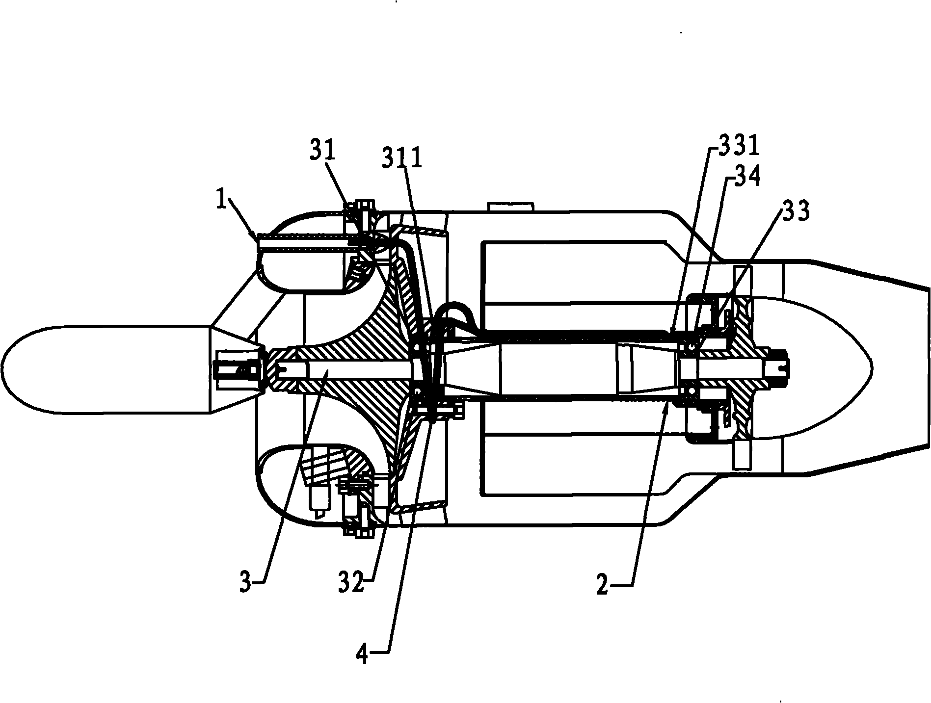
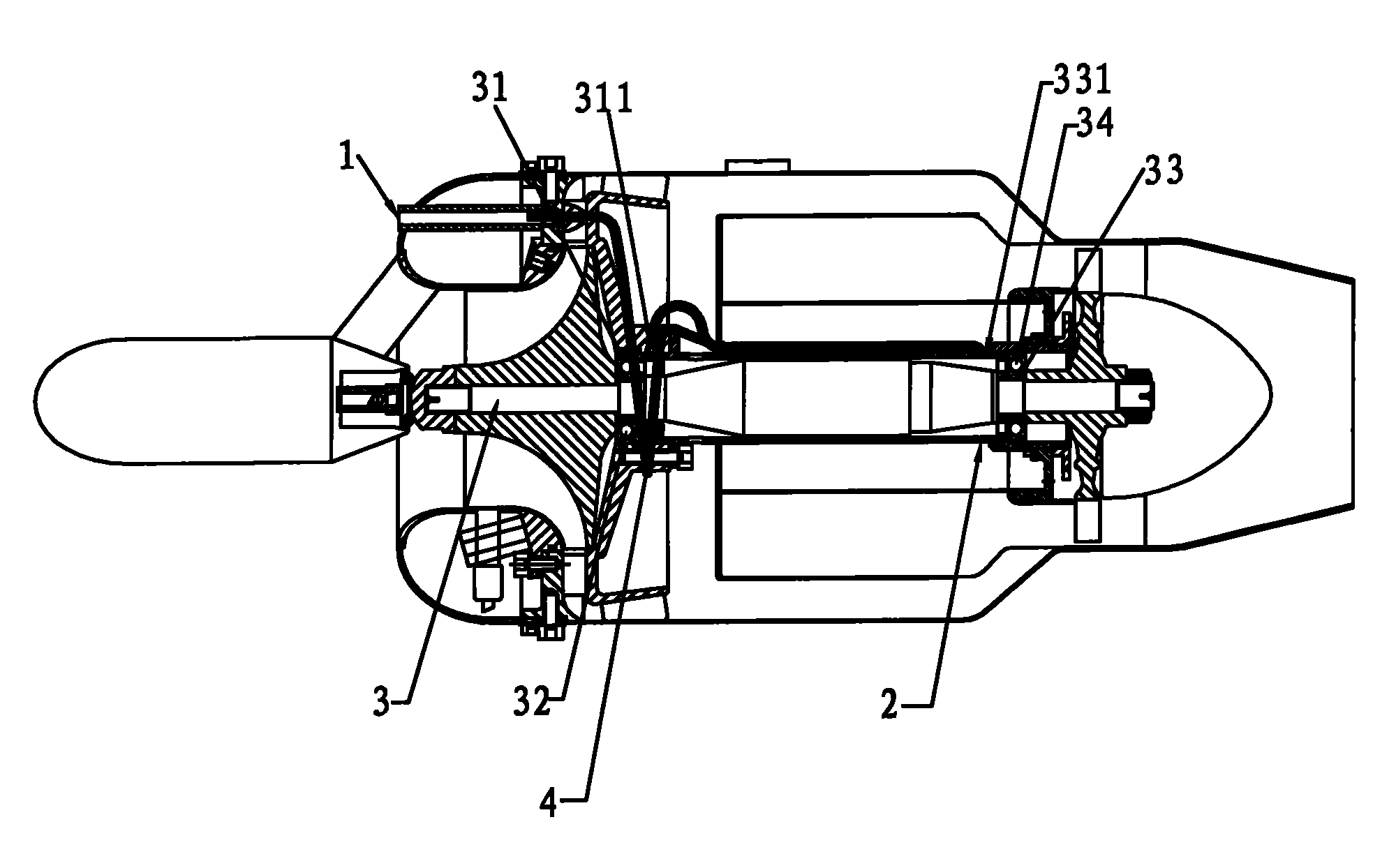
[0017] A kind of turbojet engine bearing lubricating device, as figure 1 Shown, it is to be provided with oil inlet 1 on the turbojet engine, and axle sleeve 2 is arranged in the turbojet engine, a main shaft 3 is set in the axle sleeve 2, the front end of main shaft 3 is provided with front bearing seat 31 and front The bearing 32 and the rear end of the main shaft 3 are provided with a rear bearing seat 33 and a rear bearing 34 . On the described axle sleeve 2, a slanted hole is provided at a position close to the rear bearing seat 33 to be the oil inlet 331 of the rear bearing, and in the turbojet engine, a slanted hole is also provided at the position close to the front bearing seat 31 to be the oil inlet of the front bearing. 311.

[0018] The present invention is provided with a lubricating oil pipe 4 in the oil inlet 1, adopts the principle of atomization lubrication, and can lubricate the rear bearing 34 and the front bearing 32 while the fuel is supplied for combusti...


PUM


Abstract

The invention discloses a bearing-lubricating device of a turbojet engine. The turbojet engine is provided with an oil inlet, and a lubricating oil tube is arranged from the oil inlet to the interior of the turbojet engine; a bushing is arranged in the turbojet engine, a spindle is arranged in the bushing, the front end of the spindle is provided with a front bearing pedestal and a front bearing, the rear end of the spindle is provided with a rear bearing pedestal and a rear bearing, the bushing is provided with a rear-bearing oil inlet close to the position of the rear bearing pedestal, and a front-bearing oil inlet is arranged at a position in the turbojet engine, which is close to the front bearing pedestal. A dedicated lubricating system or lubricating oil tank does not need to be arranged on the outside of the bearing-lubricating device, the bearings can be lubricated as long as lubricant is added in aviation kerosene according to an appropriate proportion, thereby, the bearing-lubricating device has convenient use and good lubricating effect.

Description

technical field [0001] The invention relates to a bearing lubricating device, in particular to a turbojet engine bearing lubricating device. Background technique [0002] When the engine is working, many transmission parts make high-speed relative motion under a small gap. Although the working surfaces of these parts are finely machined, they are uneven when viewed under magnification. If these surfaces are not lubricated, intense dry friction will occur between them. The dry friction between the metal surfaces not only increases the power consumption of the engine and accelerates the wear of the working surface of the parts, but also may burn the working surfaces of the parts due to the heat generated by the friction, causing the engine to fail to run. [0003] The function of the lubrication system is to continuously deliver a sufficient amount of clean engine oil at an appropriate temperature to the friction surfaces of all transmission parts when the engine is working,...

Claims


Application Information

Patent Timeline
IPC IPC(8): F02C7/06
Inventor 梁锡武
Owner SHENZHEN ANTUOSHAN TECH
Learn More