
Solar charging system, device and method for tracking maximum power point thereof

A technology of maximum power point and charging system, which is applied in the field of solar power generation, can solve problems such as the decline of maximum power tracking effect, and achieve good steady-state performance and dynamic performance

Active Publication Date: 2010-09-22
EMERSON NETWORK POWER CO LTD
View PDF1 Cites 18 Cited by
  • Summary
  • Abstract
  • Description
  • Claims
  • Application Information

AI Technical Summary

Problems solved by technology

The incremental conductance method has a better maximum power tracking effect when the light intensity is strong, and the algorithm can stabilize to the maximum power point when the light intensity is stable. The disadvantage of the algorithm is that the maximum power tracking effect decreases when the light intensity is low.

Method used


Image

  • Solar charging system, device and method for tracking maximum power point thereof
  • Solar charging system, device and method for tracking maximum power point thereof
  • Solar charging system, device and method for tracking maximum power point thereof

Examples


Embodiment Construction

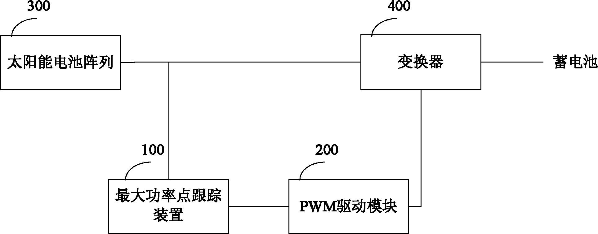
[0063] exist figure 2 In the logic diagram of Embodiment 1 of the solar charging system shown in the present invention, the solar charging system includes a solar cell array 300, a maximum power tracking point device 100, a PWM drive module 200 and a converter 400, wherein the maximum power tracking point device 100 controls the PWM driving module 200 according to the sampled voltage and current output by the solar cell array, so that the PWM driving module 200 outputs a PWM driving signal with a corresponding duty ratio to the converter 400, and the converter 400 drives the PWM according to the corresponding duty ratio. The signal converts the voltage output by the solar battery array 300 and outputs it to the storage battery. It should be noted that, to ensure that the solar cell array 300 works at the maximum power point, it is necessary to ensure that the solar cell array 300 outputs the voltage corresponding to the maximum power point to the converter 400, and the batter...


PUM


Abstract

The invention relates to a solar charging system, a device and a method for tracking a maximum power point thereof. In the method, first-side regulation comprises: performing first change on the output voltage of a current solar battery array and carrying out second-side regulation if the power after the first change is judged to be lower than that before the first change; or setting current dutycycle as the duty cycle of a maximum power point and repeating first-side regulation if the power after the first change is judged to be not lower than that before the first change; and the second-side regulation comprises: performing second change on the output voltage of the current solar battery array and carrying out the first-side regulation if the power after the second change is judged to be lower than that before the second change; or setting the current duty cycle as the duty cycle of the maximum power point and repeating second-side regulation if the power after the second change isjudged to be not lower than that before the second change. The technical scheme of the invention has good steady-state performance and dynamic performance of tracking the maximum power point.

Description

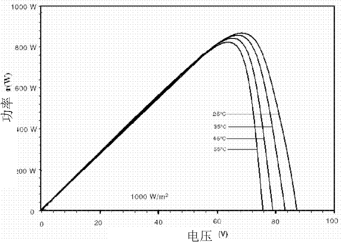
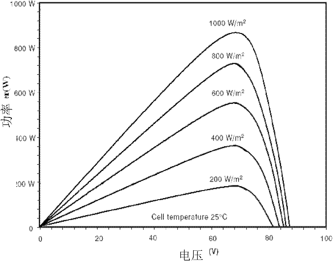
technical field [0001] The invention relates to the field of solar power generation, more specifically, to a solar charging system and its maximum power point tracking device and method. Background technique [0002] With the continuous development of society, energy issues have become more and more important, especially the accumulation of energy crises caused by the continuous reduction of non-renewable energy sources, which makes the development of new energy sources the main task at present. Solar energy is a new Energy has the advantages of being inexhaustible, inexhaustible and non-polluting, and is one of the important ways to solve energy problems in the future. [0003] Solar photovoltaic power generation is a way to convert sunlight energy into electrical energy through solar panels. According to the output characteristics of solar cells, there is a unique maximum power point for solar cells. Figure 1A is the same light intensity (1000W / m 2 ) curves of power vers...

Claims


Application Information

Patent Timeline
Patent Type & Authority Applications(China)
IPC IPC(8): H02N6/00H02S40/30
CPCY02E10/58Y02E10/56
Inventor 余恒张永辉
Owner EMERSON NETWORK POWER CO LTD
Learn More