Lip seal

A technology of lip seals and sealing components, which is applied in the direction of engine seals, bearing components, engine components, etc., can solve the problems of reduced sealing performance, sealing lip 82 foaming, etc., and achieve the effect of resource reuse

Active Publication Date: 2010-09-22
EAGLE INDS
View PDF6 Cites 11 Cited by
  • Summary
  • Abstract
  • Description
  • Claims
  • Application Information

AI Technical Summary

Problems solved by technology

In the above-mentioned bonded lip seal under such use conditions, since the rubber-like elastic sealing lip 82 and the metal reinforcing ring 84 are bo...

Method used


Image

  • Lip seal
  • Lip seal
  • Lip seal

Examples


Embodiment

[0098] Next, embodiments of the present invention will be described with reference to the drawings.

no. 1 example

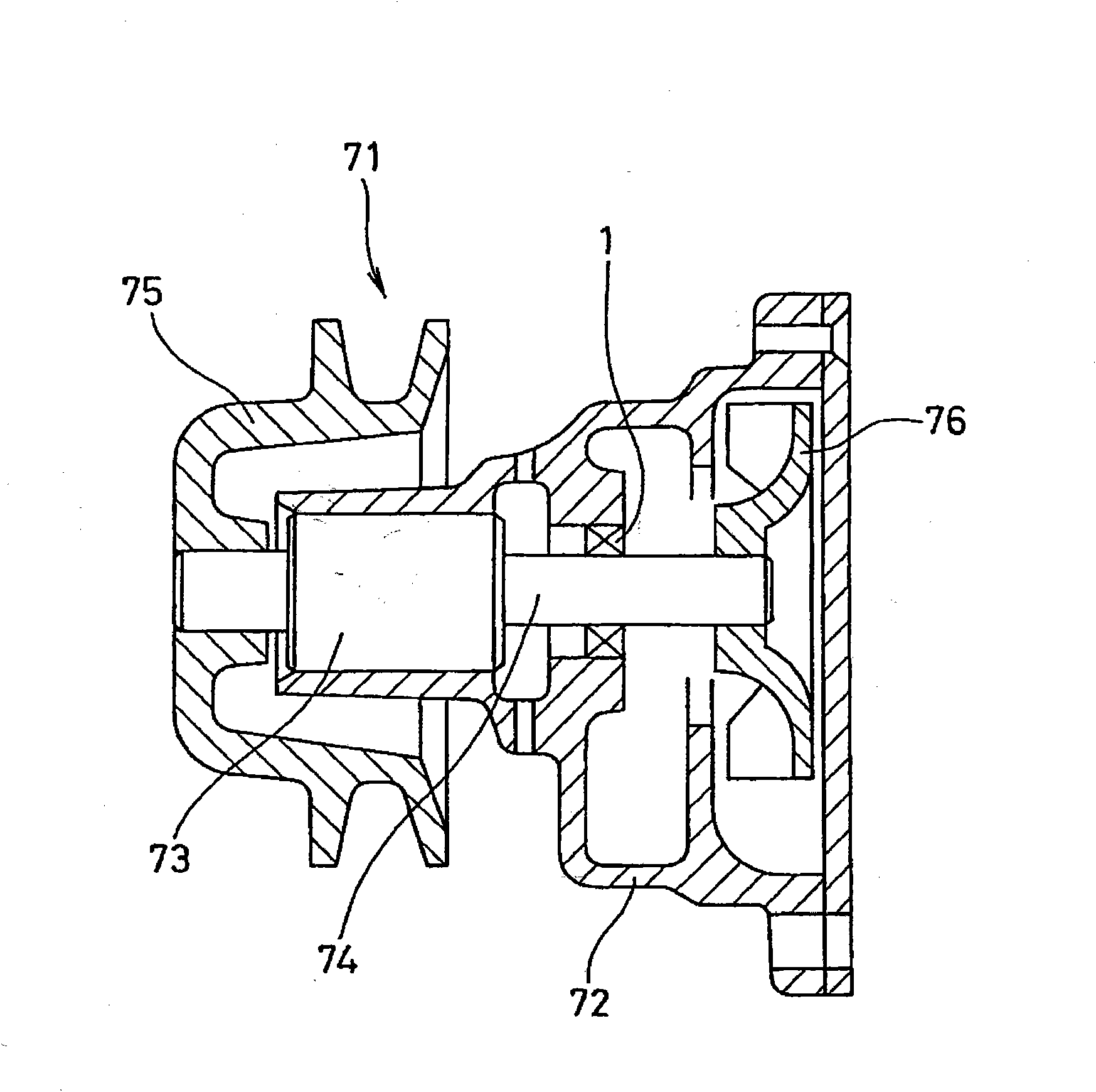
[0100] figure 1 Shown is an overall view of a water pump 71 equipped with a lip seal 1 according to the first embodiment of the present invention, that is, one end of a shaft (rotation shaft) 74 rotatably supported by a casing (casing) 72 via a bearing 73 is fixed with a The pulley 75 is fixed with an impeller 76 at the other end. When the driving torque is transmitted to the pulley 75, the impeller 76 rotates to send cooling water under pressure. The lip seal 1 is mounted on the inner periphery of the shaft hole of the casing 72 and is slidably in close contact with the peripheral surface of the shaft 74, thereby preventing the sealing fluid (cooling water) inside the machine from leaking to the atmosphere side (bearing side).

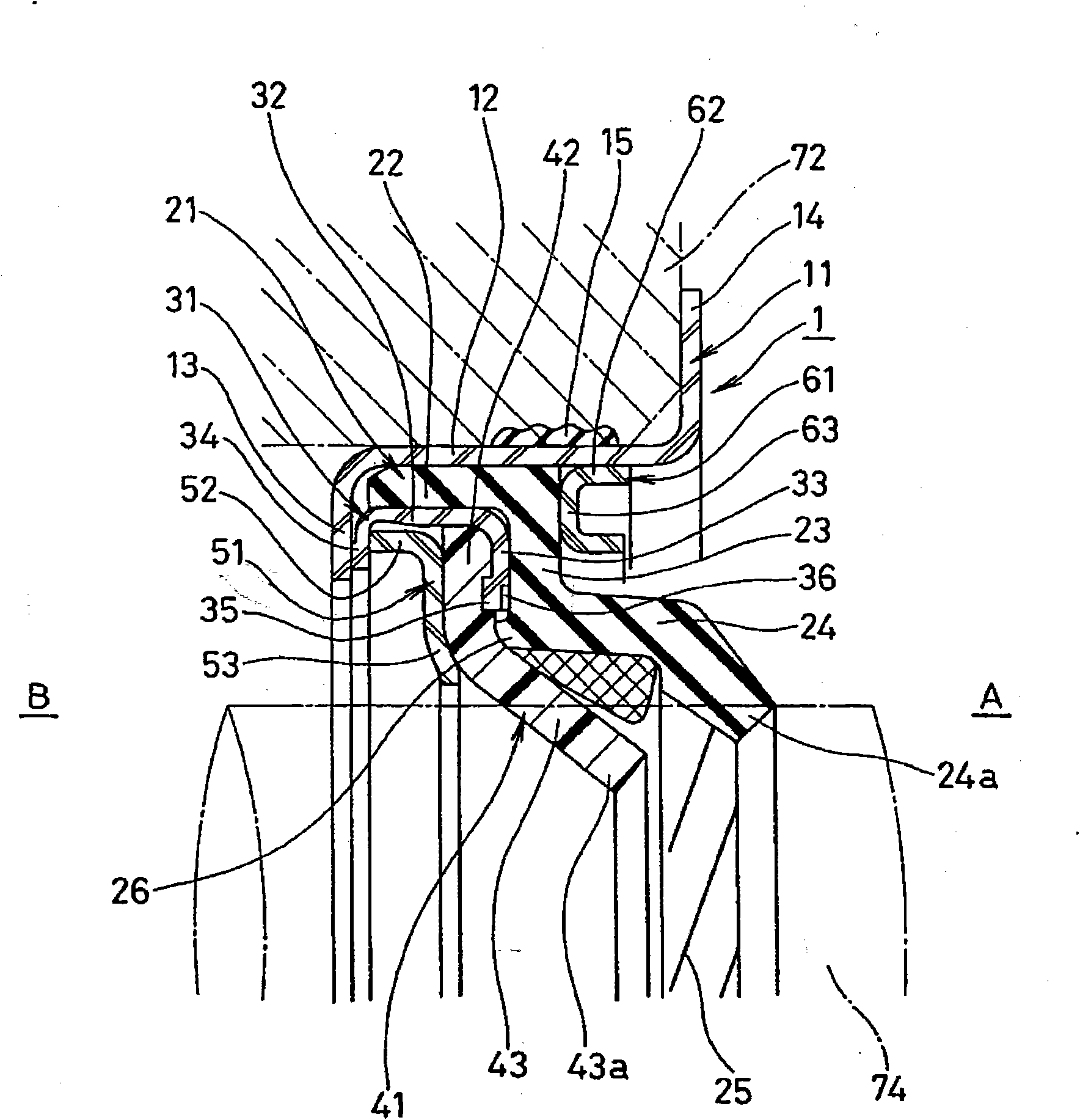
[0101] figure 2 A main part cross section of the lip seal 1 of this first embodiment is shown, and the lip seal 1 is constituted as follows. The right side of the figure is the seal fluid side A, and the left side of the figure is the atmospheric ...

no. 2 example

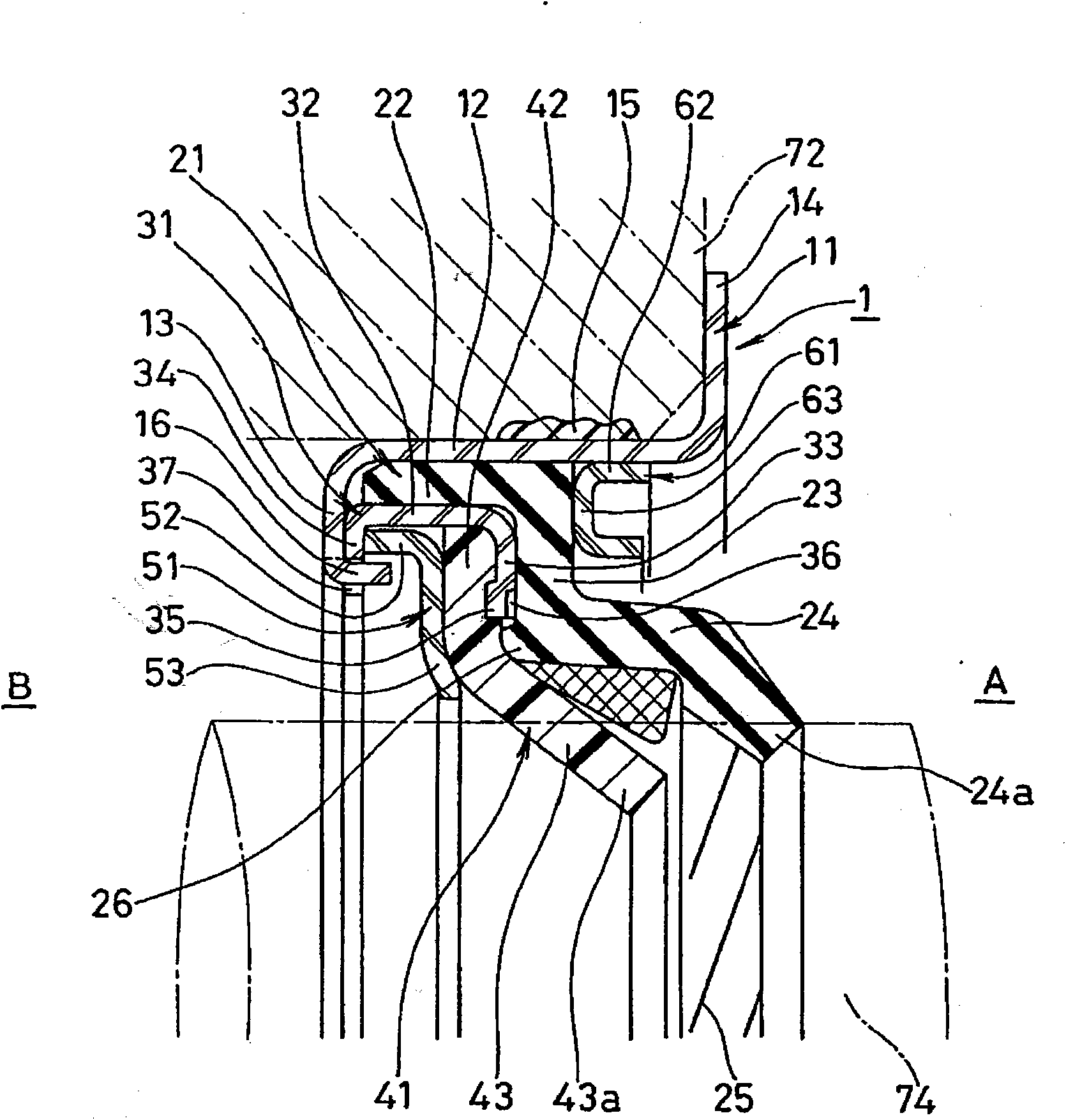
[0124] Although the above-mentioned first embodiment is configured such that the flange portion 13 of the sleeve 11 and the second flange portion 34 of the case 31 are in contact with each other in the axial direction, when the rotation preventing structure is provided here, it is possible to effectively prevent the The assembly formed by the second lip seal member 41 , the support ring 51 , and the housing 31 is co-rotated by sliding the shaft 74 . image 3 This is the second embodiment, which is provided with a rotation preventing structure such that a part of the claw portion 16 on the circumference is provided on the inner peripheral edge portion of the flange portion 13 of the sleeve 11 while corresponding to the claw portion 16 on the shell 31. The inner peripheral portion of the second flange portion 34 is provided with a notch portion 37 , and the claw portion 16 is bent toward the sealing fluid side A and engaged with the notch portion 37 to prevent rotation of the sle...


PUM


Abstract

A lip seal, wherein a first lip seal member consisting of a rubber-like elastic body is configured to be easily mounted to a cartridge to enable the roundness and coaxiality of a seal lip of the first seal lip member to be reliably maintained. A lip seal is mounted to the inner periphery of a shaft hole in a housing so as to be in slidable close contact with the peripheral surface of a shaft, and by this, the lip seal minimizes outward leakage of fluid sealed in a machine. The lip seal is provided with a cartridge fitted to the inner periphery of the shaft hole, a first lip seal member fitted to the cartridge without adhesion thereto and consisting of a rubber-like elastic body, a case fitted to the first lip seal member without adhesion thereto, a second lip seal member staked to and held by the case and consisting of a resin, a backup ring for supporting the second lip seal member, and an adapter fitted, on the sealed fluid side of the first lip seal member, to the cartridge.

Description

technical field [0001] The present invention relates to a lip seal as a kind of sealing device. The lip seal of the present invention is used, for example, as a shaft seal of a water pump (W / P) for vehicles such as automobiles, or as a shaft seal of a W / P for home appliances or light-duty industries. Background technique [0002] Since before, as Figure 9 As shown, there is known a lip type that is installed on the inner periphery of the shaft hole 72a of the casing 72 and is slidably in close contact with the peripheral surface of the shaft 74 inserted through the shaft hole 72a to suppress leakage of the sealing fluid in the machine to the atmosphere side. A seal 81 having a first seal lip 82 made of rubber-like elastic disposed on the side A of the sealing fluid and a second seal lip 83 made of resin disposed on the side B of the atmosphere (refer to Patent Document 1) . [0003] Since the above-mentioned conventional lip seal 81 has a plurality of sealing lips 82 and ...

Claims


Application Information

Patent Timeline
IPC IPC(8): F16J15/32F16C33/72F16J15/3232F16J15/3256F16J15/328
CPCF16J15/322F16J15/3232F16J15/3228
Inventor 板谷壮敏川井英生塔本英树赤木久之
Owner EAGLE INDS
Why Eureka
Try Eureka