Clamping device

A clamping device and clamping piece technology, applied in the field of elastic clamping pieces

Active Publication Date: 2010-09-29
PEISELER
View PDF7 Cites 2 Cited by
  • Summary
  • Abstract
  • Description
  • Claims
  • Application Information

AI Technical Summary

Problems solved by technology

But this results in only relatively small frictional forces being available for spindle clamping, because in this known clamping device, the friction surface is determined by the thickness of the tensioning element.

Method used


Image

  • Clamping device
  • Clamping device
  • Clamping device

Examples


Embodiment Construction

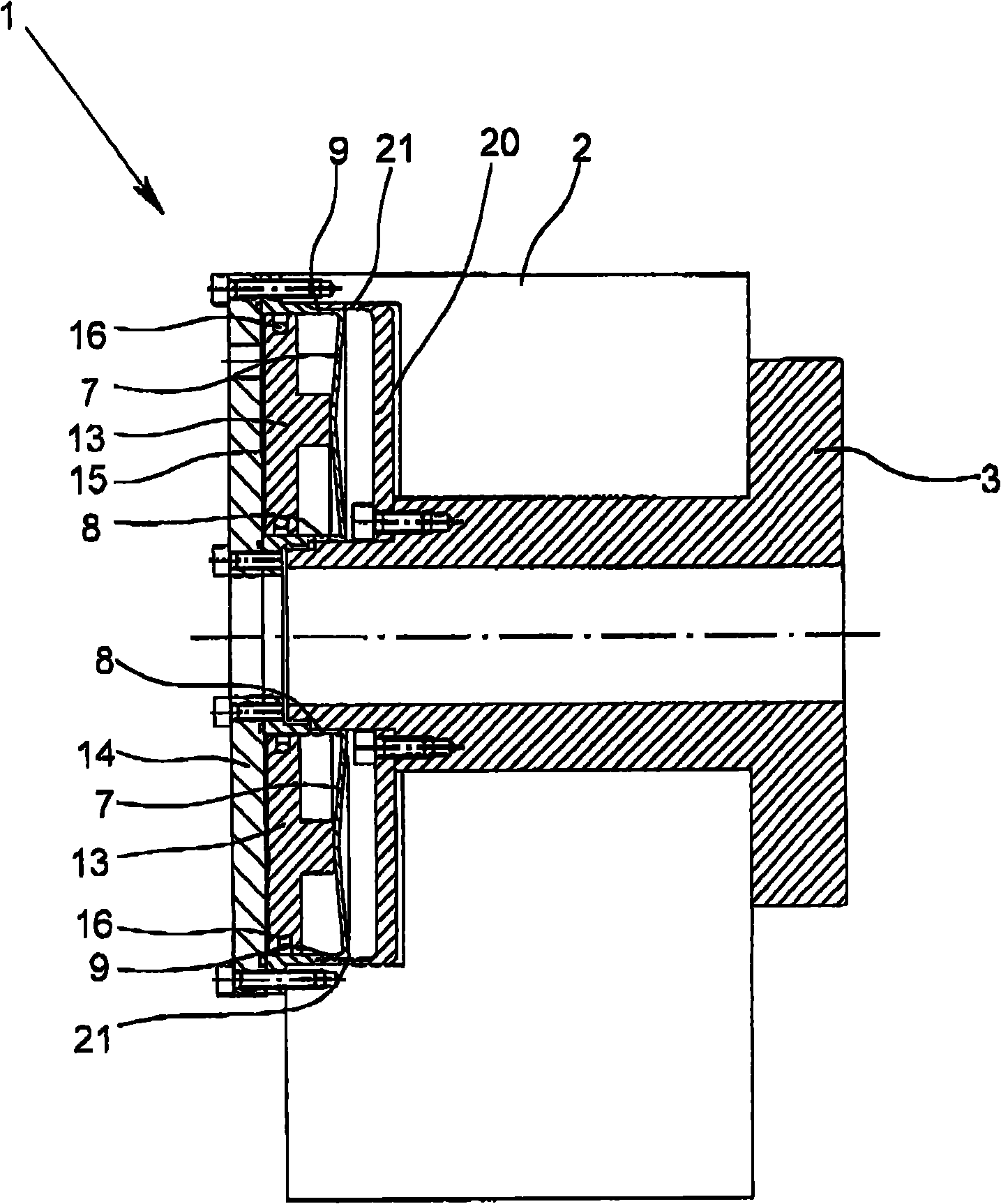
[0035] figure 1 A first exemplary embodiment of a clamping device is shown as part of the indexing device 1 , wherein the housing 2 , the spindle 3 mounted rotatably in the housing 2 and the elastic clamping part 4 belong to the clamping device. The housing 2 that is functionally associated with the clamping device is at the same time the housing 2 of the indexing device, wherein the housing 2 itself can also consist of a plurality of housing parts, which are connected to one another, in particular screwed or welded.

[0036] figure 1 The indexing device 1 shown serves to fix a clamped workpiece in any angular position of the spindle 3 so that the workpiece can then be processed in the desired position by means of a processing machine such as a milling machine, a drilling machine or a grinding machine. For positioning the workpiece, the indexing device 1 has a drive, wherein in the exemplary embodiment shown the drive is a worm gear. In order to fix the workpiece to be machi...


PUM


Abstract

A clamping device with a housing, a spindle which is rotationally mounted in the housing, and an elastic clamping element, the clamping element being movable by application of a force out of a first position in which the spindle can be turned into a second position in which the spindle is clamped by the clamping element. The clamping element has an inner cylinder which surrounds the spindle to be clamped, an outer cylinder which is located coaxially to the inner cylinder, and a membrane which connects the inner cylinder to the outer cylinder. The clamping element is annular and roughly cup-shaped with an opening in the middle of the clamping element so that the inner cylinder surrounds the spindle to be clamped. The clamping element is shaped and arranged such that, by applying a force to the clamping element the curvature of the membrane can be changed.

Description

technical field [0001] The invention relates to a clamping device with a housing, a main shaft rotatably supported in the housing and an elastic clamping member, wherein the clamping member can be moved from a first position into a second position by force, in the first position, The spindle is rotatable, while in the second position the spindle is clamped by the clamping element. Furthermore, the invention also relates to an elastic clamping element for use in a clamping device having a housing and a spindle mounted rotatably in the housing. Background technique [0002] Clamping devices are used in particular in circular indexing tables or indexing devices, whereby a clamped workpiece is positioned in a desired angular position in order to be able to subsequently process the workpiece. The workpiece can now be set horizontally or vertically according to the design of the circular indexing table or indexing device. The clamping device must exert a sufficiently high clampi...

Claims


Application Information

Patent Timeline
Patent Type & Authority Applications(China)
IPC IPC(8): F16B1/02B23Q16/00B23Q1/26B23Q1/48
CPCF16D2121/02F16D49/00B23Q16/10B23Q1/287F16D2125/12F16D2125/68Y10T24/44641
Inventor B·科里谢姆H·霍尔特
Owner PEISELER
Why Eureka
Try Eureka