
Optical touch system and optical touch positioning method

An optical touch and optical unit technology, applied in instruments, computing, electrical digital data processing, etc., can solve the problems of complex structure, complex equipment, high cost, reduce environmental interference, reduce the thickness of the frame, and improve the accuracy.

Active Publication Date: 2010-09-29
LENOVO (BEIJING) CO LTD
View PDF0 Cites 23 Cited by
  • Summary
  • Abstract
  • Description
  • Claims
  • Application Information

AI Technical Summary

Problems solved by technology

The cost of this implementation depends on the precision and computing power of the camera, and in order to capture the entire touch area, the camera needs to be set far away from the device where the touch area is located. The entire device is complicated and not easy for users to use. higher cost
[0005] In the process of realizing the present invention, the inventor found that the current optical touch system still has defects such as complex structure, inconvenient application for users, high cost, and poor anti-interference.

Method used


Image

  • Optical touch system and optical touch positioning method
  • Optical touch system and optical touch positioning method
  • Optical touch system and optical touch positioning method

Examples


Embodiment Construction

[0066] The present invention will be further described below in conjunction with the accompanying drawings and specific embodiments.

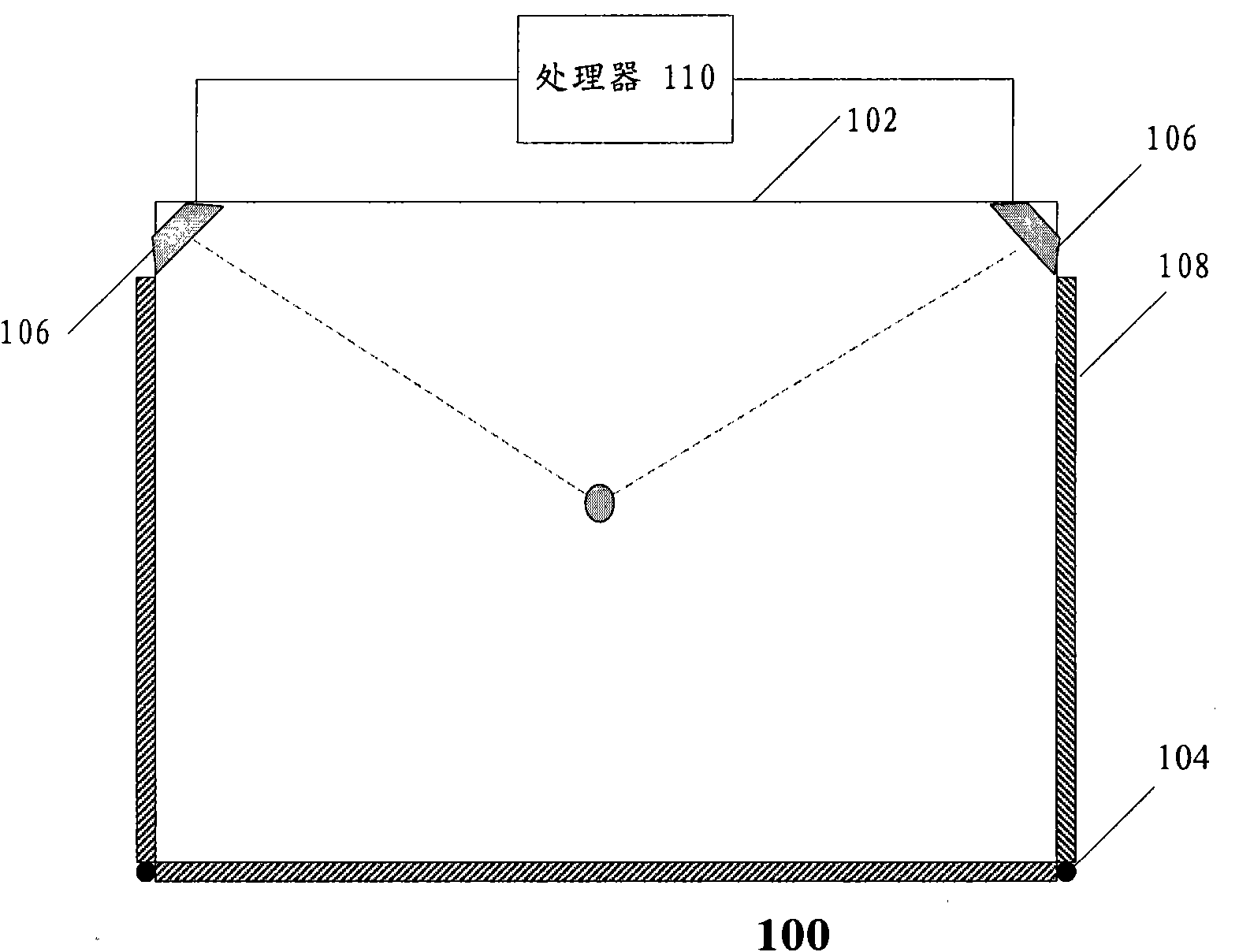
[0067] figure 1 is a schematic diagram of an optical touch system according to an embodiment of the present invention;

[0068] Such as figure 1 As shown, in this embodiment, the optical touch system 100 is applied to a display, and it is arranged on the edge of the display screen, including: a point light source 104, which is arranged at two vertices on the lower side of the display screen; a light guide plate 108, It is arranged on the left side, the right side and the lower edge of the display side of the display screen, and the end surface of the light guide plate at the apex of the lower side of the display screen is opposite to the point light source, so that the light emitted by the point light source Light enters the light guide plate and scatters to the display screen through the light guide plate, and the upper side of the light gui...


PUM


Abstract

The invention provides an optical touch system applied to electronic equipment with at least one physical surface. The optical touch system comprises an optical unit, an image acquisition unit and a processing unit, wherein the optical unit is arranged on the physical surface and used for generating a first optical effect, the image acquisition unit is arranged on the physical surface, at least partial optical unit is arranged in an acquisition range of the image acquisition unit, a touch operation area is formed by the image acquisition unit and the optical unit, the image acquisition unit is used for capturing second optical effect images which are formed on the first optical effect after an operator for operating the electronic equipment enters the touch operation area, and the processing unit is connected with the image acquisition unit and used for confirming an operator range in the touch operation area according to the second optical effect images. The invention also provides optical touch input display equipment and an optical touch input positioning method. The touch system has low cost and high reliability.

Description

technical field [0001] The invention relates to an optical touch system and an optical touch positioning method. Background technique [0002] There are two types of touch technologies commonly used at present: capacitive touch and optical touch. [0003] Capacitive touch needs to attach a transparent conductive material to the screen, which is expensive, and because the capacitance changes with temperature, humidity or grounding conditions, its stability is poor, and drifting often occurs. [0004] On the other hand, an optical touch screen needs to arrange a camera above the screen to collect finger motion images and complete finger positioning based on complex analysis of finger motion images. The cost of this implementation depends on the precision and computing power of the camera, and in order to capture the entire touch area, the camera needs to be set far away from the device where the touch area is located. The entire device is complicated and not easy for users to...

Claims


Application Information

Patent Timeline
IPC IPC(8): G06F3/042G06F3/02
CPCG06F3/0428
Inventor 杨锦平尚可杰明
Owner LENOVO (BEIJING) CO LTD
Learn More