
Electric connection device of base and main body

An electrical connection device and an electrical connection technology are applied in the direction of the two-part connection device, the parts of the connection device, and the connection. It can solve the problems of insufficient redundant space, burnout of the LED light, and inconvenient indication, etc., to achieve functional diversity, Improved flexibility and comfortable use

Active Publication Date: 2010-09-29
谛卓(北京)咨询顾问有限公司
View PDF4 Cites 12 Cited by
  • Summary
  • Abstract
  • Description
  • Claims
  • Application Information

AI Technical Summary

Problems solved by technology

[0002] The cordless 360-degree rotating electric kettle currently on the market is divided into a base and a main body. The base and the main body are directly connected through a coupler. The coupler includes signal connections for live wire, neutral wire and ground wire. The input power is from The base transmits the power to the main body to supply the heating device on the main body. The heating device realizes the operation of the electric kettle and automatically cuts off the power under the cooperation of the switch. At the same time, according to the national standard, an indicating device is required for display when the electric kettle is working. Whether the heater is working or not is currently displayed by lights, such as neon lights or LED lights. Since the main body contains a heating device, the LED lights are difficult to withstand high temperatures. Therefore, LED lights often burn out due to high temperatures, and , in order to observe whether the indicator light is working or not from any angle, it is necessary to install more lights at different angles. However, due to the lack of extra space on the main body, generally only 1-2 lights are installed to indicate Not convenient enough to observe from any angle

Method used


Image

  • Electric connection device of base and main body
  • Electric connection device of base and main body
  • Electric connection device of base and main body

Examples


Embodiment Construction

[0015] For the convenience of explanation, the present invention refers to the electric kettle as the object of specific implementation, and the object of the present invention may include other heating devices or electric devices other than the electric kettle.

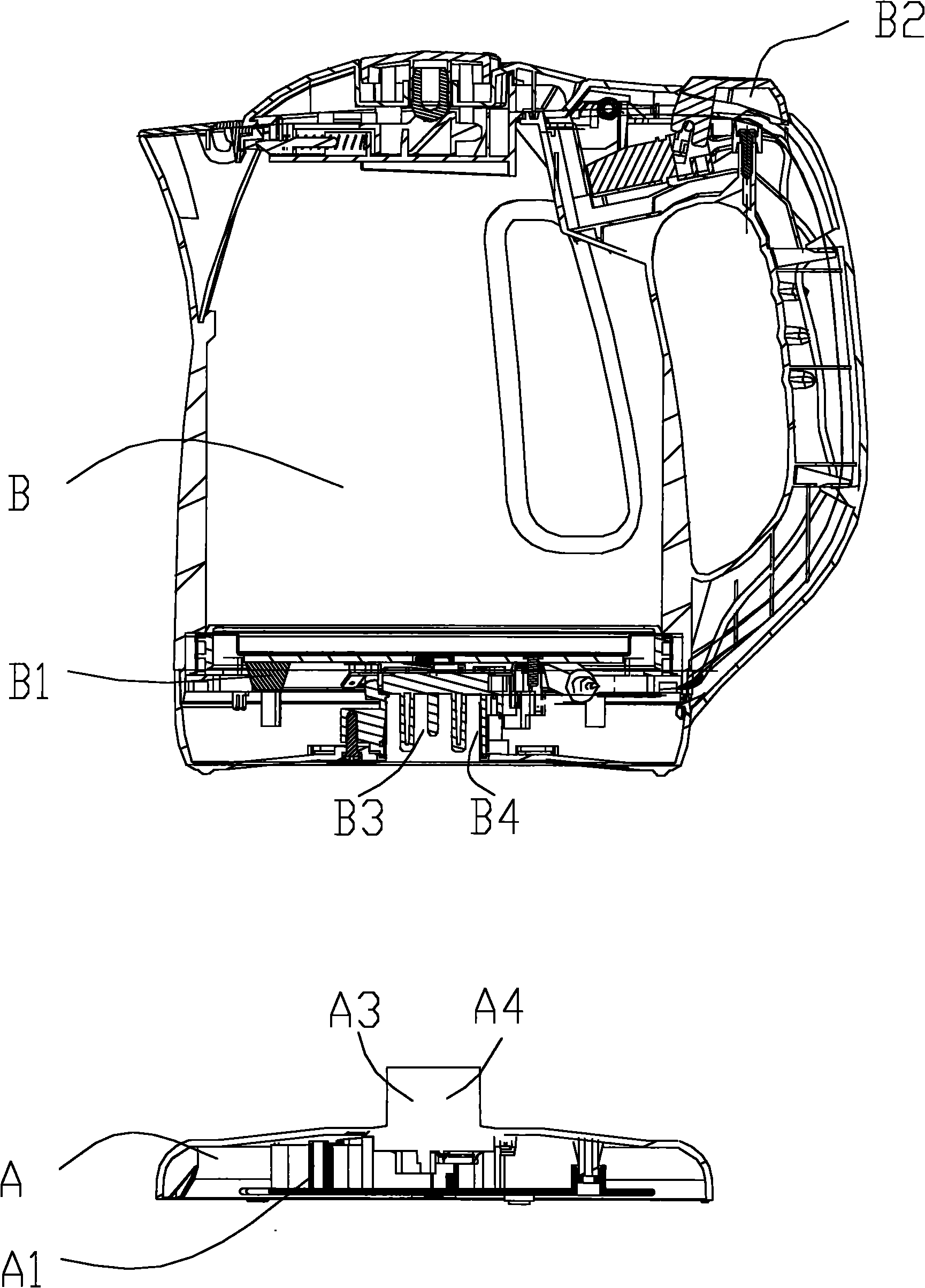
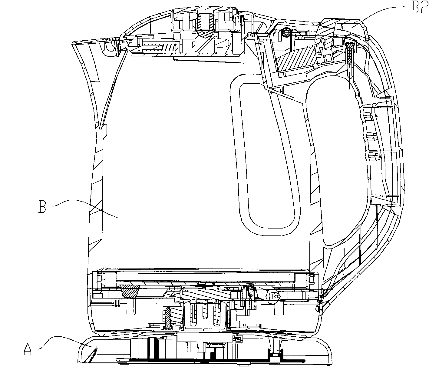
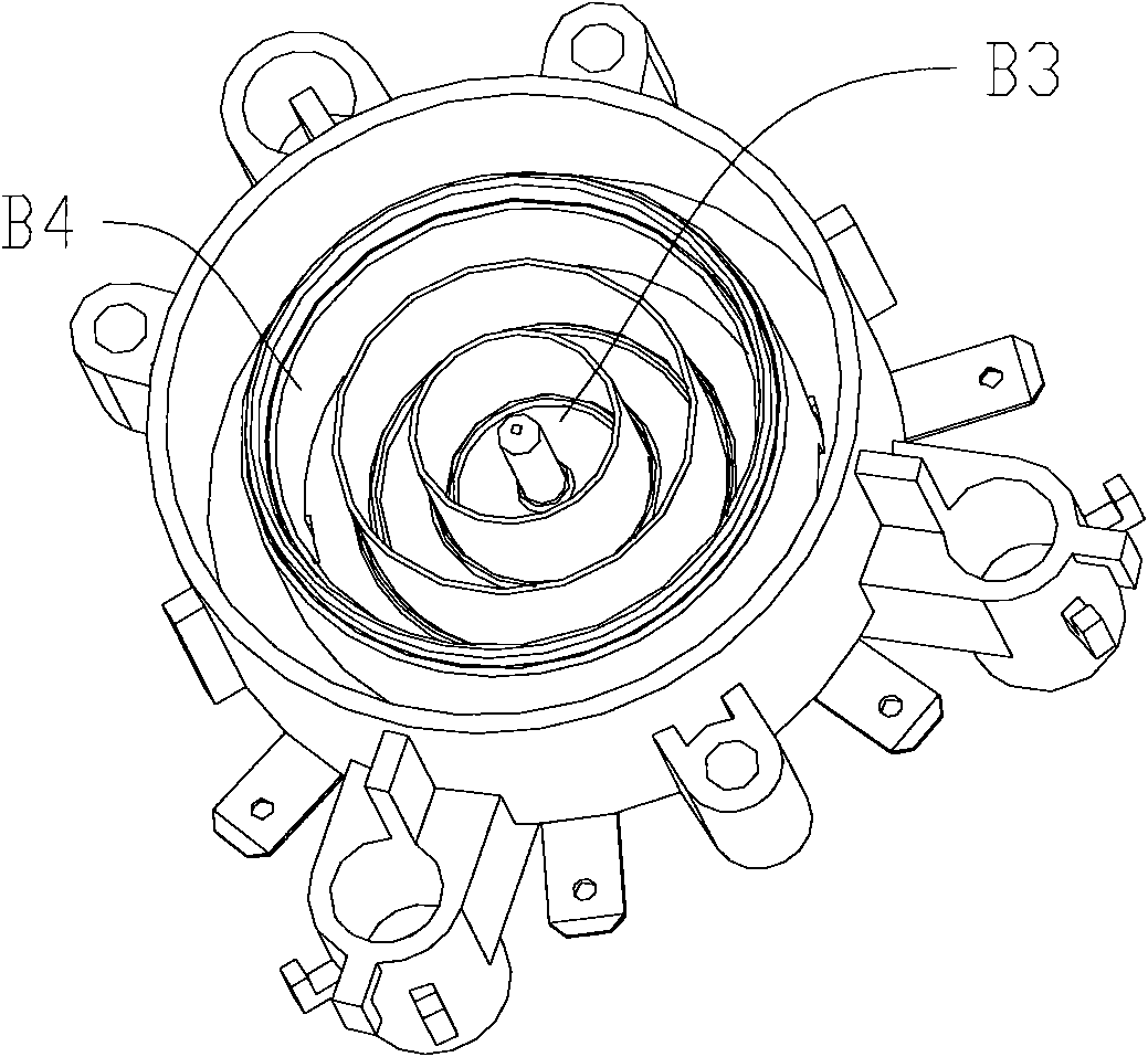
[0016] The electric kettle includes a base A and a main body B, and the base A and the main body B are connected through a first coupler; the first coupler includes a first connector A3 provided on the base A and a first connector A3 provided on the main body B The first appliance socket B3 of the main body B includes the working load B1; the input power is transmitted to the first appliance socket B3 through the first connector A3 of the base A, and is directly or indirectly electrically connected with the working load B1 of the main body B A second coupler is also connected between the base A and the main body B, the base A is provided with an electrical response device A1, and the working state of the main body B i...


PUM


Abstract

The invention relates to an electric connection device of a base and a main body, which comprises a base and a main body, wherein the base and the main body are connected by a first coupler; the first coupler comprises a first connector and a first appliance socket, wherein the first connector is arranged on the base, and the first appliance socket is arranged on the main body; the main body comprises a working load; an input power supply is transmitted onto the first appliance socket by the first connector of the base and is electrically connected with the working load of the main body directly or indirectly; and a second coupler is also connected between the base and the main body, an electric response device which responds the working state of the main body is arranged in the base, andthe working state of the main body is transmitted to the electric response device of the base by the second coupler. The invention realizes the display of the working state of the main body on the base, overcomes the problem of too high temperature rise or space insufficiency because the electric response device is arranged on the main body, can realize the diversification of a display mode and enhances the flexibility of the design of the main body part of a product greatly.

Description

technical field [0001] The invention belongs to the field of electrical devices, in particular to an electrical connection device between a base and a main body. Background technique [0002] The cordless 360-degree rotating electric kettle currently on the market is divided into a base and a main body. The base and the main body are directly connected through a coupler. The coupler includes signal connections for live wire, neutral wire and ground wire. The input power is from The base transmits the power to the main body to supply the heating device on the main body. The heating device realizes the operation of the electric kettle and automatically cuts off the power under the cooperation of the switch. At the same time, according to the national standard, an indicating device is required for display when the electric kettle is working. Whether the heater is working or not is currently displayed by lights, such as neon lights or LED lights. Since the main body contains a h...

Claims


Application Information

Patent Timeline
IPC IPC(8): H01R24/00H01R33/945H01R13/717A47J27/21
Inventor 谭发刚林小艺
Owner 谛卓(北京)咨询顾问有限公司
Learn More