
110V passive high-power factor circuit

A 1.110V, high-power technology, used in light sources, electric light sources, electrical components, etc., can solve the problems of high power consumption of the whole lamp and low power factor of PPFC circuits, so as to improve power factor, reduce current harmonics, and improve switching. effect of times

Inactive Publication Date: 2010-09-29
HANGZHOU EBOYLAMP ELECTRONICS CO LTD
View PDF3 Cites 0 Cited by
  • Summary
  • Abstract
  • Description
  • Claims
  • Application Information

AI Technical Summary

Problems solved by technology

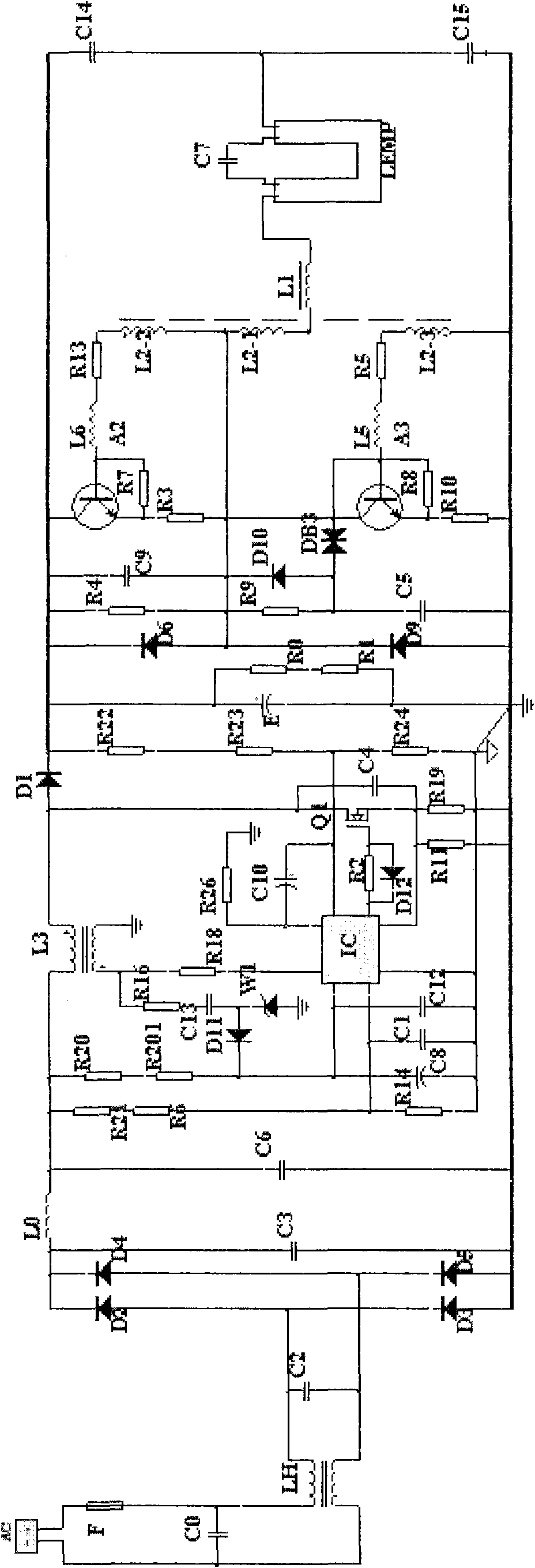
[0006] The invention solves the technical problem of low power factor and high power consumption of the whole lamp in the previous high-frequency pump PPFC circuit, and provides a passive high power factor circuit mainly used in energy-saving lamps with a rated voltage of 110V~127V. Improve the power factor of the circuit, reduce the lamp current peak ratio and current harmonics, reduce the power consumption of the whole lamp, and increase the switching times of the whole lamp at the same time

Method used


Image

  • 110V passive high-power factor circuit
  • 110V passive high-power factor circuit
  • 110V passive high-power factor circuit

Examples


Embodiment

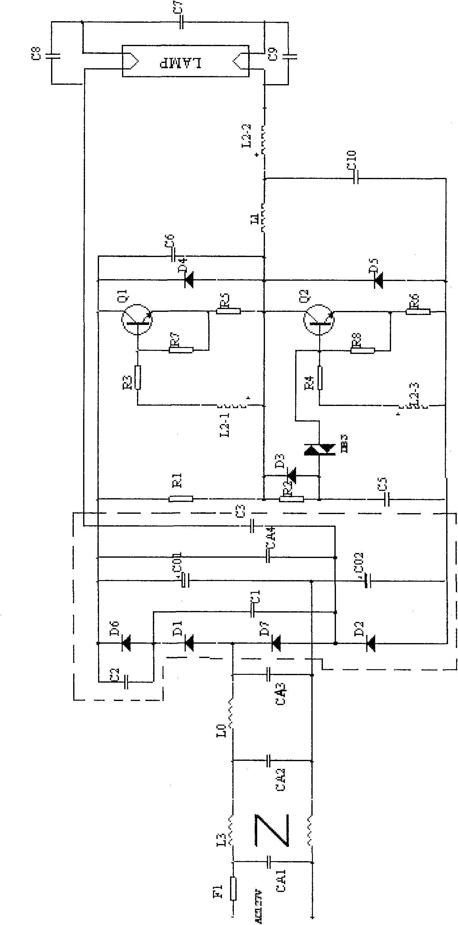
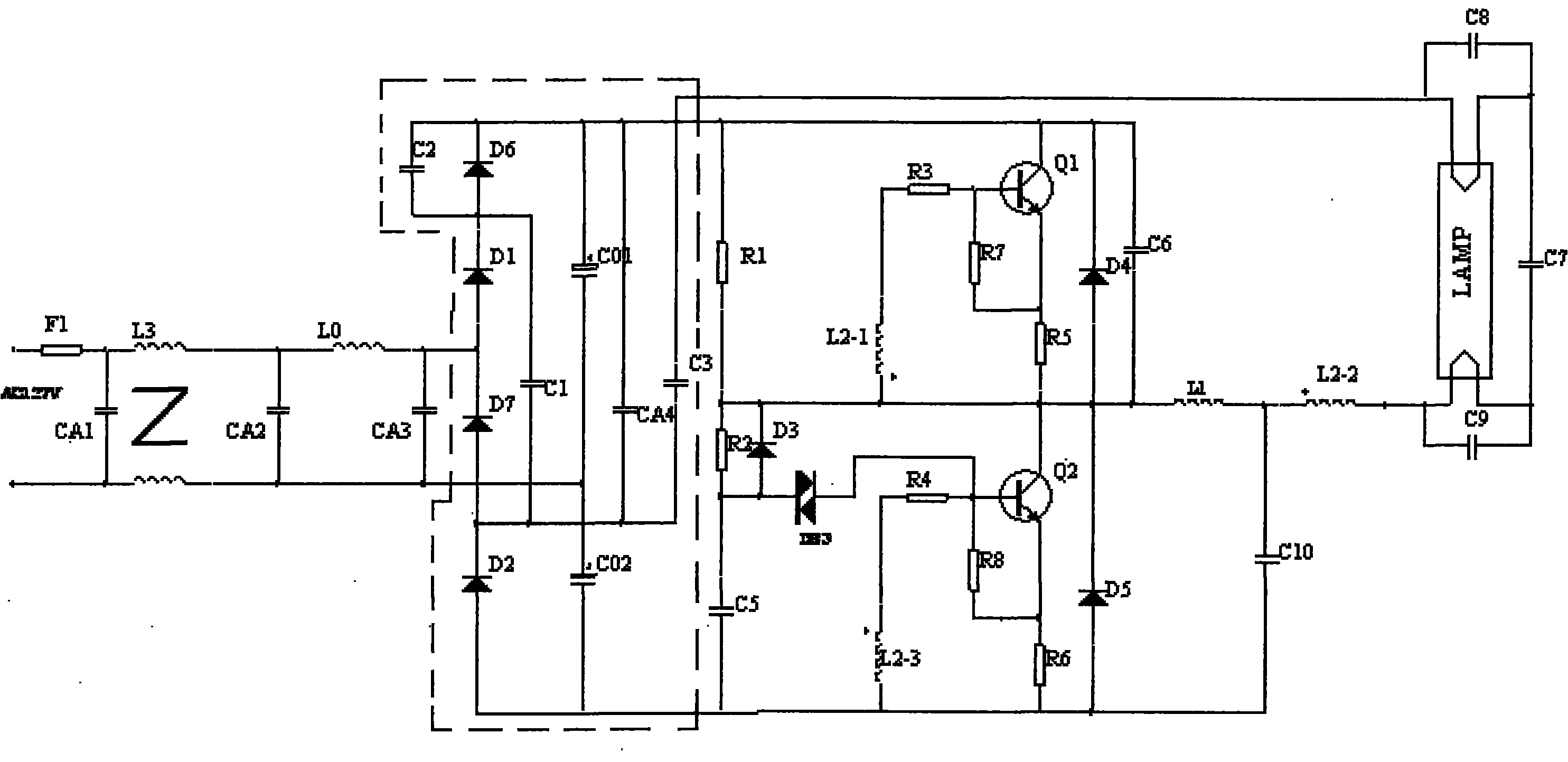
[0022] Example: such as figure 2 As shown, the 110V passive high power factor circuit includes an EMC circuit, a half-bridge circuit, a series resonant circuit and a load. It is composed of inductance L2-2 and capacitor C7. Its function is to generate the starting high voltage required by the lamp; the input ends of the EMC circuit are connected to the input ends of the power supply, and power factor correction is connected between the EMC circuit and the half-bridge circuit. circuit, the power factor correction circuit includes a diode D2, a diode D7, a diode D1, a diode D6, an electrolytic capacitor CO1, and an electrolytic capacitor CO2, wherein the diode D2, the diode D7, the diode D1, and the diode D6 are sequentially connected in series, and the electrolytic capacitor CO1 Connect the diode D2, diode D7, diode D1, and diode D6 in series with the electrolytic capacitor CO2, connect the negative pole of the electrolytic capacitor CO1 to the positive pole of the electrolyti...


PUM


Abstract

The invention discloses a 110V passive high-power factor circuit, comprising an EMC (Electro Magnetic Compatibility) circuit, a power factor correction circuit, a semi-bridge circuit, a serial resonant circuit and a load, wherein the power factor correction circuit comprises a diode D2, a diode D7, a diode D1 and a diode D6 which are sequentially connected in series; an electrolytic capacitor CO1is connected in series with an electrolytic capacitor CO2 and is then connected in parallel with the diode D2, the diode D7, the diode D1 and the diode D6; a capacitor C1 is connected between the cathode of the diode D1 and the anode of the diode D7; and a capacitor C3 is connected among the anode of the diode D7, the cathode of the diode D2 and the anode of the diode D7. The high-frequency current of a light tube is fed back through the capacitor C3 to form a negative voltage drop, so that the electrolytic capacitor CO2 is always kept in a charging state in the negative semi-cycle of inputting alternating current; and the high-frequency current on the C3 passes through the C1 to form positive voltage on the D6, so that the CO1 is always kept in a charging state in the positive semi-cycleof a power supply, thereby improving the power factor of a circuit.

Description

technical field [0001] The invention relates to the related technical field of electronic ballasts, in particular to a passive high power factor circuit in the electronic ballasts. Background technique [0002] With the shortage of energy in the world, electronic ballasts have been widely used. At present, various manufacturers are making various efforts to improve the power consumption of energy-saving lamps, prolong the service life of lamps, and improve the power factor of lamps; power factor It is the ratio of the actual consumed power to the power supply capacity, so the higher the power factor is, the unnecessary loss of power can be reduced and the utilization rate of power can be improved during the transmission process. [0003] For energy-saving lamps with a rated voltage of 110V ~ 127V, especially high-power energy-saving lamps, the main way to improve the power factor in the market is to use active power factor correction to improve the power factor. The circuit ...

Claims


Application Information

Patent Timeline
Patent Type & Authority Applications(China)
IPC IPC(8): H05B41/282
Inventor 俞青松
Owner HANGZHOU EBOYLAMP ELECTRONICS CO LTD
Learn More