Guide crossbeam device for short stress bar rolling mill

A short-stress rolling mill and beam technology, applied in the direction of guiding/positioning/alignment devices, etc., can solve the problems of low slot change efficiency, high maintenance cost, and low slot change efficiency, and achieve long maintenance intervals and pollution resistance Good, low maintenance effect

Inactive Publication Date: 2010-10-06
WUHAN IRON & STEEL (GROUP) CORP
View PDF5 Cites 2 Cited by
  • Summary
  • Abstract
  • Description
  • Claims
  • Application Information

AI Technical Summary

Problems solved by technology

[0007] 2. Poor positioning

Method used


Image

  • Guide crossbeam device for short stress bar rolling mill
  • Guide crossbeam device for short stress bar rolling mill
  • Guide crossbeam device for short stress bar rolling mill

Examples


Example Embodiment

[0039] The present invention will be further described in detail below with reference to the accompanying drawings and embodiments, but the embodiments should not be construed as limiting the present invention.

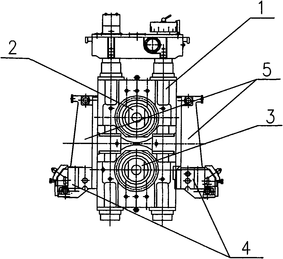
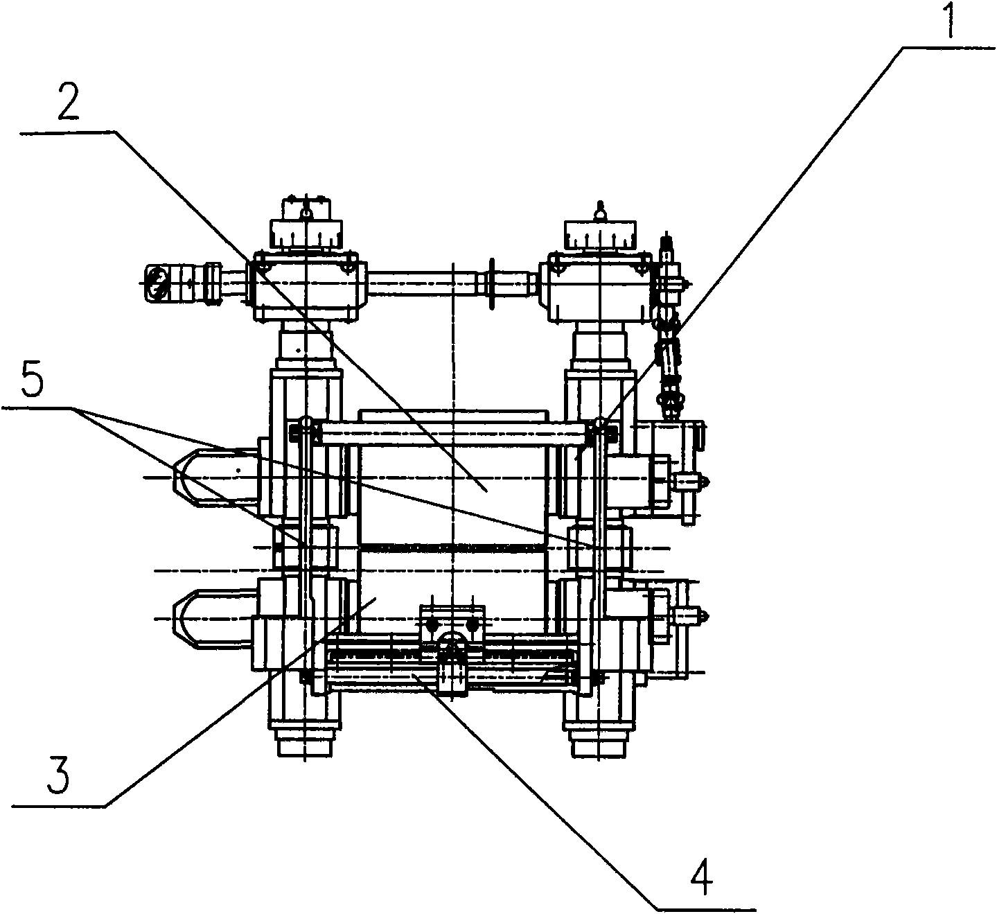
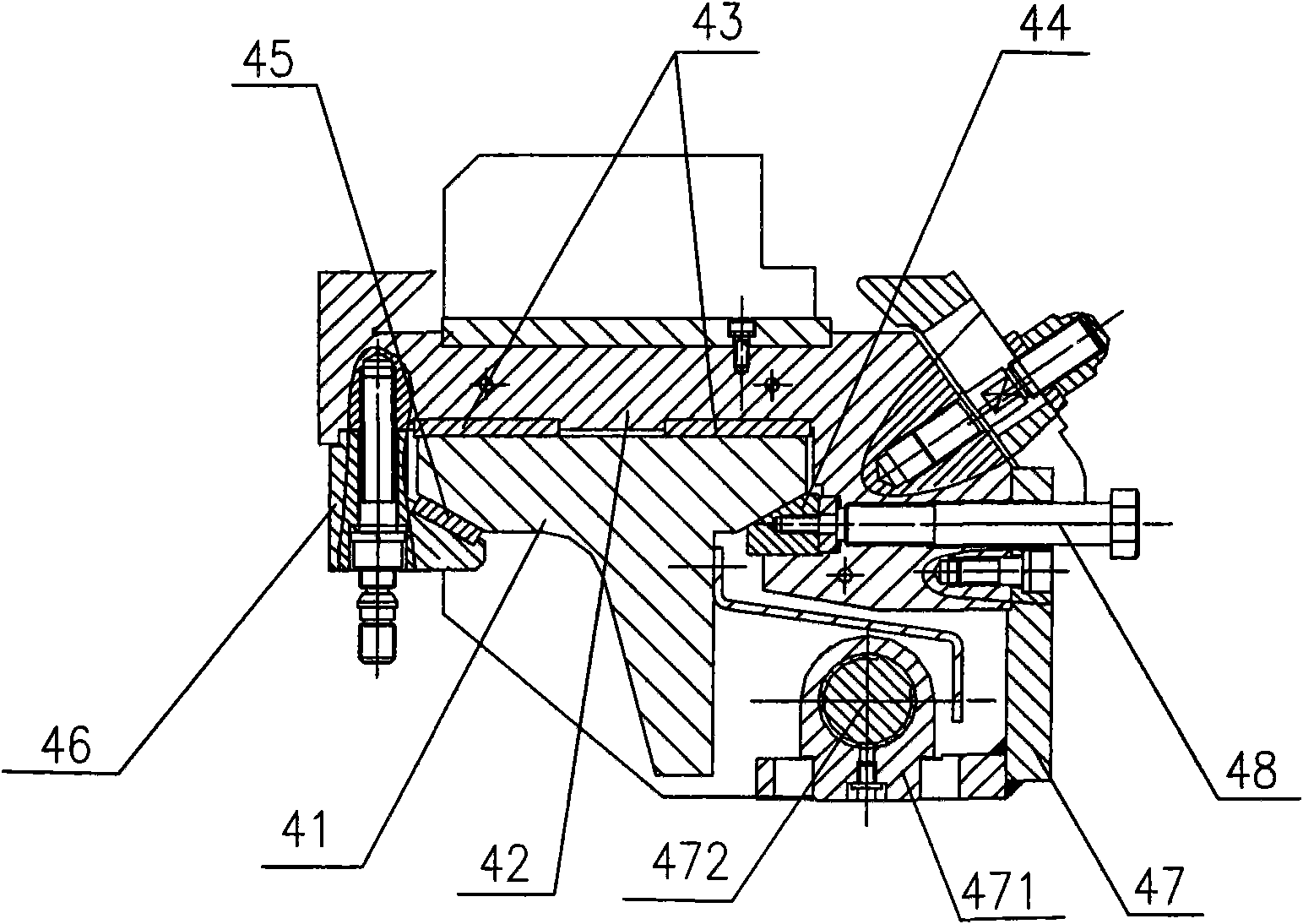
[0040] see Figure 4 and Figure 5 , the present invention is a guide beam device for a bar short stress rolling mill, including a guide beam body 41, a guide seat 42, a lower pressure plate 46, an upper inclined surface PTFE pad 8, and a lower plane PTFE Backing plate 9, worm gear rack 10, worm 12, worm bearing seat 11, locking screw 48, slag flushing slope 15, wherein the guide beam body 41 consists of left guide rail 6, right guide rail 7, worm gear rack fixing frame 13 and The rib plate 14 is formed, and the left guide rail 6 and the right guide rail 7 are located above the worm gear rack fixing frame 13 , and the three are fixed on the rib plate 14 .

[0041] The guide seat 42 is located above the guide beam body 41 . The lower left slope of the guide seat 42 ...


PUM


Abstract

The invention discloses a guide crossbeam device for a short stress bar rolling mill. The guide crossbeam device comprises a guide crossbeam body, a guide seat and a downwards-pressing plate, wherein the guide seat is positioned above the guide crossbeam body; the downwards-pressing plate is fixed on the left lower part of the guide seat; left and right inclined planes on the lower part of the guide seat are matched with left and right inclined planes on the upper part of the guide crossbeam body respectively; an upper inclined plane polytetrafluoroethylene base plate fixed between the inclined planes is in fit with upper and lower inclined planes respectively; a worm bearing pedestal is fixed on the right lower part of the guide seat; a matching plane of the downwards-pressing plate and the upper part of the guide crossbeam body, and a matching plane of the worm bearing pedestal and the upper part of the guide crossbeam body are horizontal planes; the horizontal planes of the guide crossbeam body are positioned below the inclined planes; and a lower plane polytetrafluoroethylene base plate fixed between the horizontal planes is in fit with the upper and lower horizontal planes respectively. The guide crossbeam device has the characteristics of accurate location, high pollution-resistant and self-lubricating properties of sliding planes and driving pairs, and easy movement of the guide seat, self-locking reliability, low labor intensity and short operating time during groove changing, and long maintenance period. The guide crossbeam device can be widely applied in the field of steel rolling.

Description

technical field [0001] The invention relates to a bar short-stress rolling mill, in particular to a guide beam device for the rolling mill. Background technique [0002] figure 1 and figure 2 It is a bar short-stress rolling mill commonly used in the prior art, including a rolling mill body 1, an upper roll 2 and a lower roll 3 arranged up and down in the rolling mill body 1, and racks 5 are arranged on both sides of the rolling mill body 1 along the rolling direction. Guard beam 4 device is arranged on frame 5 below. [0003] The main function of the guide crossbeam device 4 is to move the guide along the direction of roll rotation to align the roll groove when the guide is positioned and the groove is changed. image 3 It is a structural schematic diagram of the guide beam device 4 in the prior art. In the guide beam device 4 , the guide seat 42 is located above the guide beam body 41 , two horizontally placed plane copper backing plates 43 are installed between the g...

Claims


Application Information

Patent Timeline
IPC IPC(8): B21B39/14
Inventor 周文郑则学肖卫兵胡建国
Owner WUHAN IRON & STEEL (GROUP) CORP
Why Eureka
Try Eureka