
Universal rotation spherical blender

The technology of a multi-rotating ball type mixer is applied to cement mixing devices, clay preparation devices, chemical instruments and methods, etc. It can solve problems such as difficult angle adjustment, loud noise, and uneven mixing of materials, so as to save maintenance time and reduce The effect of using cost and improving production efficiency

Inactive Publication Date: 2010-10-06
台德恩
View PDF4 Cites 9 Cited by
  • Summary
  • Abstract
  • Description
  • Claims
  • Application Information

AI Technical Summary

Problems solved by technology

[0002] At present, the commonly used concrete mixers mainly have the following three structural forms. 1. The single-horizontal shaft concrete mixer, because the blades are easy to wear, the gap is getting larger and larger, and there is a problem of uneven mixing.
2. Vertical concrete forced mixer, due to the wear of the blades and the dead angle in front of the shovel, the material mixing is not uniform
3. Hemispherical mixer, due to the wear of the mixing shovel, it is difficult to adjust the angle, the worm gear and worm at the bottom of the pot are easy to wear, and the material is stirred unevenly; and because the processing of the pot is easy to eccentric, the gap at the edge is large, and the stirring noise is also very large , easy to collapse
The above three mixers all have the problems of loud noise, difficult unloading, and difficult cleaning of the pot
[0003] Chinese patent specification CN200720012495.5 discloses a universal ball mixer, although it can make the materials in the pot fully mixed, but it has the following disadvantages: 1. When the spherical pot rotates, it is in contact with the small wheel supporting the pot Friction produces a lot of noise; 2: The stirring fin is not elastic, and it will break or be stuffy, which will affect the stirring effect; frequent maintenance of the stirring fin or motor is required, the work efficiency is low, and the production cost is high

Method used


Image

  • Universal rotation spherical blender
  • Universal rotation spherical blender
  • Universal rotation spherical blender

Examples


Embodiment Construction

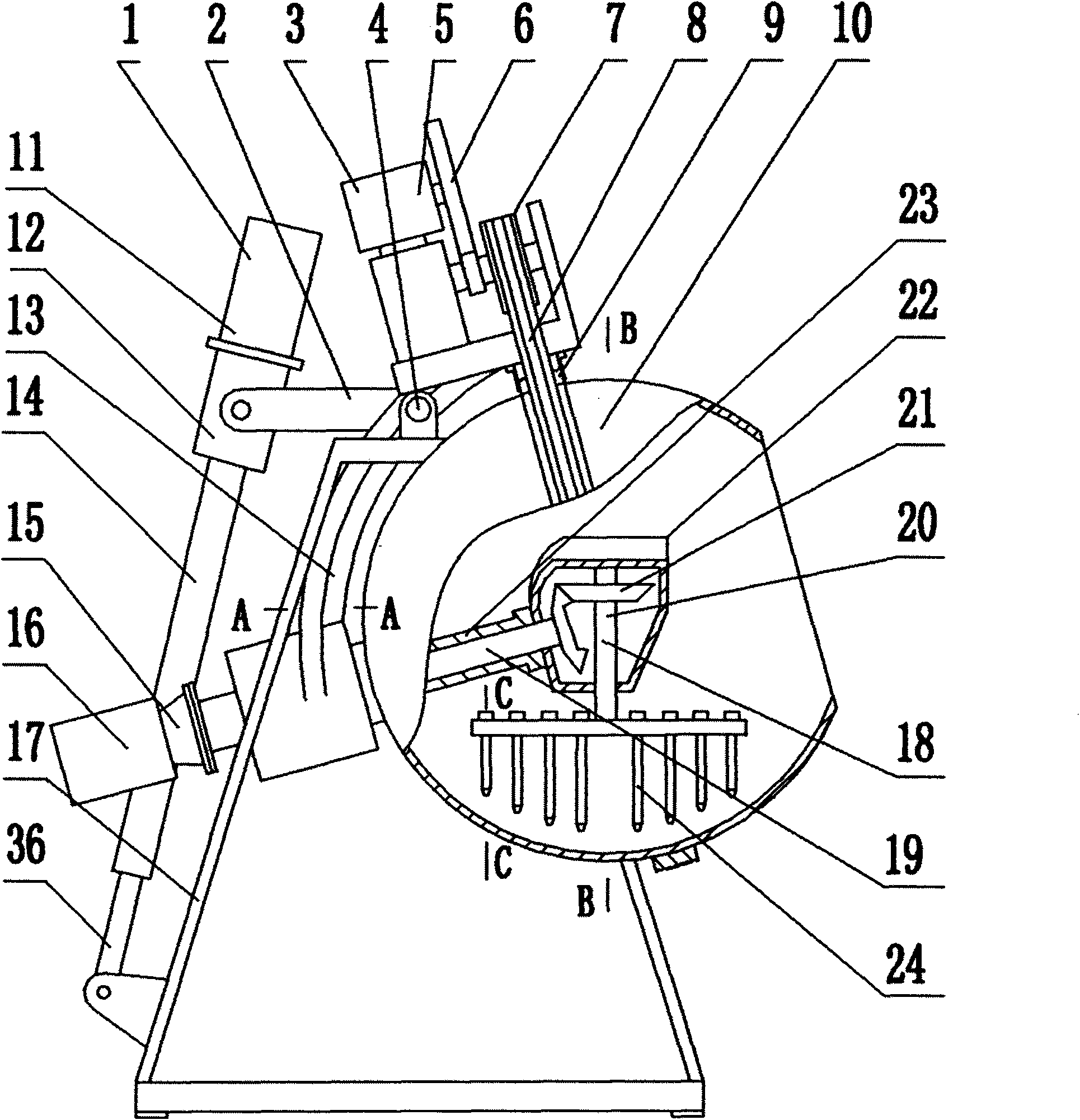
[0017] The present invention comprises machine base 17, support 13, spherical pot body 10, stirring mechanism 18, rotating mechanism 3 and overturning mechanism 1, and support 13 is installed on the machine base 17 by rotating shaft 4, can rotate relative to machine base 17, spherical shape The pot body 10 is fixed on the support 13, and the rotating mechanism 3 includes a rotating motor 5, a transmission gear 6, and a main pulley 7 which are arranged on the support 13 and are connected successively. Pulley 7 and belt 8 from pulley 9.

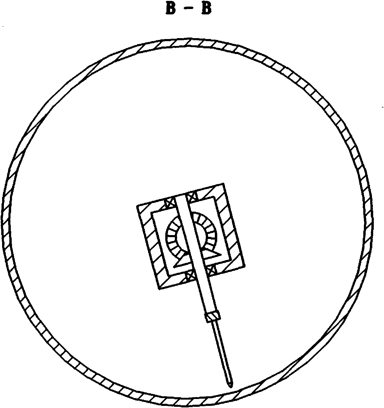
[0018] The stirring mechanism 18 includes a motor 16, a reducer 15, a driving shaft 19, a driven shaft 20 and a stirring fin 24 connected in sequence, and the driving shaft 19 and the driven shaft 20 are meshed and connected by a gear 21; the stirring fin 24 is arranged on the driven shaft 18 The lower end is composed of a beam 25 , a plurality of tines 27 arranged on the beam 25 and a plug 31 , and a spring 29 is arranged in the tines 27 and t...


PUM


Abstract

The invention relates to a universal rotation spherical blender, in particular to a universal rotation spherical blender with low noise, low operation cost, high operational efficiency and good blending effect. The universal rotation spherical blender comprises a base, a bracket which can rotate relative to the base, and a spherical pan body, a blending mechanism, a rotating mechanism and a turnover mechanism which are fixed on the bracket. The universal rotation spherical blender is structurally characterized in that the rotating mechanism comprises a rotating motor, a transmission gear and a driving belt pulley which are arranged on the bracket and are sequentially connected, a driven belt pulley arranged on the spherical pan body and a belt connecting the driving belt pulley with the driven belt pulley. The blending mechanism comprises a motor, a reducer, a driving shaft, a driven shaft and blending fin which are sequentially connected, and the driving shaft is connected with the driven shaft by gear engagement; and the blending fin is arranged at the lower end of the driven shaft and consists of a beam and a plurality of prongs and screwed plugs, the prongs and pipe plugs are arranged on the beam, and springs are arranged in the prongs and the pipe plugs.

Description

technical field [0001] The invention relates to a mixer, in particular to a multi-rotating ball mixer suitable for production and experiments. Background technique [0002] At present, the commonly used concrete mixers mainly have the following three structural forms. 1. The single-horizontal shaft concrete mixer has the problem of uneven mixing because the blades are easy to wear and the gap is getting larger and larger. 2. For the vertical concrete forced mixer, due to the blade wear and the dead angle in front of the shovel, the material mixing is not uniform. 3. Hemispherical mixer, due to the wear of the mixing shovel, it is difficult to adjust the angle, the worm gear and worm at the bottom of the pot are easy to wear, and the material is stirred unevenly; and because the processing of the pot is easy to eccentric, the gap at the edge is large, and the stirring noise is also very large , easy to collapse. The above three mixers all have the problems of loud noise, di...

Claims


Application Information

Patent Timeline
IPC IPC(8): B28C5/18
Inventor 台德恩张欢杨奎民杨国涛杨柳赵鼎王瑞芳王树全刘士军卞婧杨欢刘福波高强杨有义刘俊文刘桂英葛军
Owner 台德恩
Learn More