

Method for modeling milling force in peripheral milling process
A modeling method and milling force technology, applied in special data processing applications, instruments, electrical and digital data processing, etc., can solve the problems of poor prediction accuracy of milling force models, and achieve the effect of saving test costs.
Active Publication Date: 2010-10-06
NORTHWESTERN POLYTECHNICAL UNIV
View PDF2 Cites 31 Cited by
- Summary
- Abstract
- Description
- Claims
- Application Information
AI Technical Summary
Problems solved by technology
In order to overcome the deficiency of poor prediction accuracy of the milling force model established in the milling process by the existing method, the present invention provides a milling force modeling method in the circumferential milling process
Method used
View moreImage
Smart ImageViewing Examples


Examples
Embodiment 2
Embodiment 3
Login to View More PUM
 Abstract
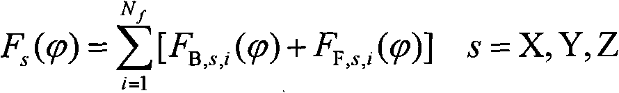
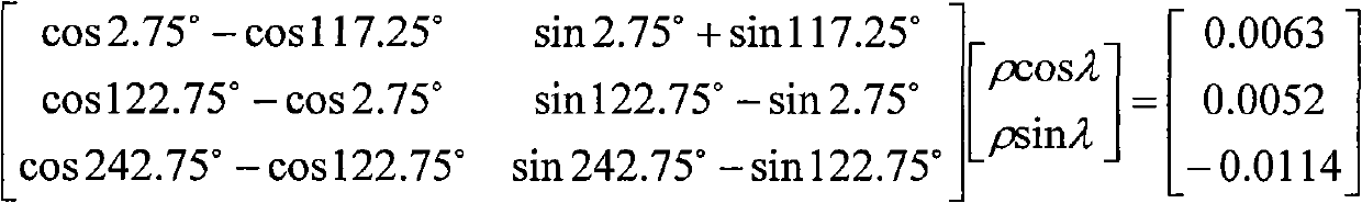
The invention discloses a method for modeling a milling force in a peripheral milling process, which aims to solve the technical problem of the poor prediction precision of a milling force model established in the milling process in the conventional methods. In the method, the milling force model simultaneously comprising side-blade cutting and bottom-blade cutting is established so as to overcome the shortcoming that only the side-blade cutting is taken into account in the peripheral milling force modeling process in the conventional methods. Compared with the prior art, the method has the advantages of simplifying an equality relation A between a measured force and a predicted force as cutter eccentricity parameters are first determined, and allowing that the cutter is axially cut-in and divided into a plurality of sections in a calibration test to make a cutting-in depth equal to any value meeting conditions so as to make the calibration test more consistent with an actual machining state; and due to the adoption of a direct calibration method, all parameters in the model can be calibrated by one calibration test to save test cost.
Description
technical field The invention relates to a milling force modeling method, in particular to a milling force modeling method in the circumferential milling process. Background technique Circumferential milling is to realize part processing by cutting off excess material on the surface of the material with a circular milling cutter. It is one of the most commonly used methods for processing various convex and concave molds and aerospace parts in mechanical manufacturing. Improving processing efficiency and processing quality is the core of advanced machinery manufacturing technology. In recent years, more and more studies involving milling processing have shown that efficient milling force prediction models have important guiding significance for milling process analysis. Milling force is the basic basis for milling process parameter planning and on-line automatic control of processing quality. Its accurate prediction is very important for ensuring the surface quality of workp...
Claims
Login to View More Application Information
Patent Timeline
 Patent Type & AuthorityApplications(China)
IPC IPC(8): G06F17/50
Inventor张卫红党建卫万敏杨昀
OwnerNORTHWESTERN POLYTECHNICAL UNIV