
Method for modeling milling force in peripheral milling process

A modeling method and milling force technology, applied in special data processing applications, instruments, electrical and digital data processing, etc., can solve the problems of poor prediction accuracy of milling force models, and achieve the effect of saving test costs.

Active Publication Date: 2012-07-04
NORTHWESTERN POLYTECHNICAL UNIV
View PDF2 Cites 0 Cited by
  • Summary
  • Abstract
  • Description
  • Claims
  • Application Information

AI Technical Summary

Problems solved by technology

[0005] In order to overcome the deficiency of poor prediction accuracy of the milling force model established in the milling process by the existing method, the present invention provides a milling force modeling method in the circumferential milling process

Method used


Image

  • Method for modeling milling force in peripheral milling process
  • Method for modeling milling force in peripheral milling process
  • Method for modeling milling force in peripheral milling process

Examples


Embodiment 2

[0093] Embodiment 2: Select radius R=6mm, helix angle β. The three-tooth carbide end mill with =30° performs down-milling on aluminum alloy A17050 on a three-coordinate numerical control end milling machine. Predicted radial depth of cut R r =5mm, axial depth of cut R z = 3mm, single tooth feed rate f = 0.08mm, spindle speed v = 1000r / min, the steps of the milling force during the down milling cutting process are as follows:

[0094] (1) Select the radial depth of cut R r =6mm, axial depth of cut R z = 5mm, single tooth feed f = 0.06mm, spindle speed v = 1000r / min, carry out the calibration test.

[0095] (2) Taking the axial differential beam segment as 1mm, the corresponding sampling interval is 5.5°. Test and record milling forces Depend on Solutions have to: adopt because it is relatively and larger.

[0096] (3) will be solved Substituting the expression of the actual cutting radius of the blade, expanding and organizing according to the trigonome...

Embodiment 3

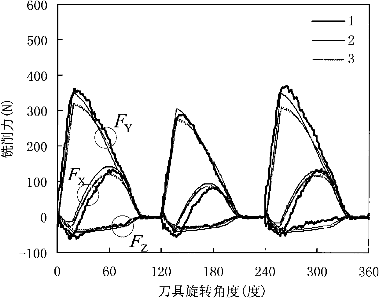
[0110] Embodiment 3: Using the cutting tool and machine tool in Embodiment 2 to mill aluminum alloy Al7050, predict the radial depth of cut R r =12mm, axial depth of cut R z = 3mm, single tooth feed rate f = 0.022mm, spindle speed v = 3000r / min milling force in the down milling cutting process.

[0111] Bring the calibration results of Example 2 into the basic milling force model to predict the milling force. From Figure 4 It can be seen from the prediction results of the milling force that the prediction accuracy of the milling force in the peripheral milling process is improved by adopting the modeling method of this embodiment.

[0112] It should be pointed out that once the tool is re-installed during machining, the previously calibrated milling force coefficient can continue to be used, but the tool eccentricity parameter must be re-calibrated.


PUM


Abstract

The invention discloses a method for modeling a milling force in a peripheral milling process, which aims to solve the technical problem of the poor prediction precision of a milling force model established in the milling process in the conventional methods. In the method, the milling force model simultaneously comprising side-blade cutting and bottom-blade cutting is established so as to overcome the shortcoming that only the side-blade cutting is taken into account in the peripheral milling force modeling process in the conventional methods. Compared with the prior art, the method has the advantages of simplifying an equality relation A between a measured force and a predicted force as cutter eccentricity parameters are first determined, and allowing that the cutter is axially cut-in and divided into a plurality of sections in a calibration test to make a cutting-in depth equal to any value meeting conditions so as to make the calibration test more consistent with an actual machining state; and due to the adoption of a direct calibration method, all parameters in the model can be calibrated by one calibration test to save test cost.

Description

technical field [0001] The invention relates to a milling force modeling method, in particular to a milling force modeling method in the circumferential milling process. Background technique [0002] Circumferential milling is to realize part processing by cutting off excess material on the surface of the material with a circular milling cutter. It is one of the most commonly used methods for processing various convex and concave molds and aerospace parts in mechanical manufacturing. Improving processing efficiency and processing quality is the core of advanced machinery manufacturing technology. In recent years, more and more studies involving milling processing have shown that efficient milling force prediction models have important guiding significance for milling process analysis. Milling force is the basic basis for milling process parameter planning and on-line automatic control of processing quality. Its accurate prediction is very important for ensuring the surface ...

Claims


Application Information

Patent Timeline
Patent Type & Authority Patents(China)
IPC IPC(8): G06F17/50
Inventor 张卫红党建卫万敏杨昀
Owner NORTHWESTERN POLYTECHNICAL UNIV
Learn More