Bi-directional tubular type induction motor for home-automation

An induction motor, dual-rotation technology, applied in asynchronous induction motors, electric components, electrical components, etc., can solve problems such as minor

Active Publication Date: 2010-10-06
SOMFY ACTIVITES SA
View PDF8 Cites 6 Cited by
  • Summary
  • Abstract
  • Description
  • Claims
  • Application Information

AI Technical Summary

Problems solved by technology

Since the motor is short, the above problem may not be serious

Method used


Image

  • Bi-directional tubular type induction motor for home-automation
  • Bi-directional tubular type induction motor for home-automation
  • Bi-directional tubular type induction motor for home-automation

Examples


Embodiment Construction

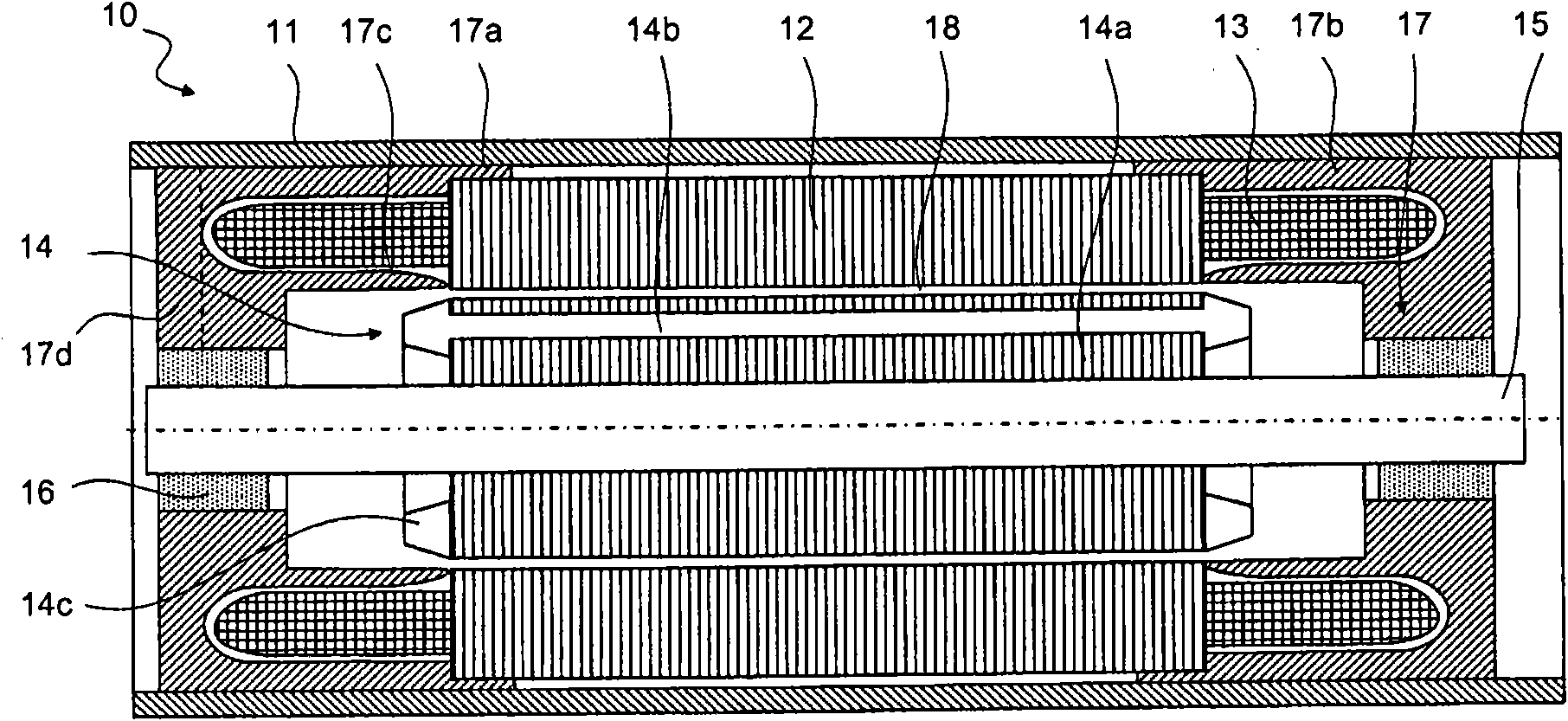
[0040] figure 1represents a longitudinal section of a tubular electric machine 10 according to the prior art. The tubular motor is inserted into an outer tube 11 which extends on both sides of the motor and is shown in cutaway form. The outer tube 11 is the tube of a tubular actuator designed to be installed in a building and comprising at least one mechanical reduction gear (not shown). The electric machine comprises a stator metal lamination stack 12 comprising teeth, not visible in this cross-sectional view, into which windings of enamelled copper wire are inserted. On the outside of the stator, turns of the coil pass from one tooth to the almost diametrically opposite other tooth, forming winding ends 13 or end windings. Depending on the kind of winding method used, "flyer" winding or conventional insertion winding, the winding ends are more or less bulky. The electric machine includes a rotor 14 attached to a shaft 15 . The rotor comprises a stack 14a of rotor metal ...


PUM


Abstract

Tubular induction motor (20; 30) with two directions of rotation, contained in a tube (11) of a tubular actuator designed to be installed in a building, comprising a squirrel cage rotor (24; 34) supported by bearings (26; 36; 46) and a stator (12) comprising a stack of metal laminations forming a central bore (12a) and centred in the tube, wherein a support part of a bearing (29; 37; 47) is centred in the central bore, wherein the bearing is of the plain and conductor type and wherein it is placed as close as possible to a short-circuiting ring (24c) of the rotor, preferably less than 2 mm and preferably less than 1 mm away.

Description

technical field [0001] The invention relates to the field of tubular motors of the induction motor type (or asynchronous motors) having a squirrel-cage rotor and two directions of rotation when designed for installation in Used in tubular actuators in buildings. Background technique [0002] A tubular motor refers to a motor that is inserted into an outer tube that contains a tubular actuator and whose stator metal lamination stack is generally longer than its outer diameter. Tubular actuators are installed in horizontal positions in buildings, for example for rolling the fabric of awnings or curtains, or for rolling roller blinds. [0003] The tubular motor is thus one of the components contained in the tube of the tubular actuator. Other components are the reduction gear and usually the control unit. The result is that the vibrations of the motors are transmitted directly or indirectly to the long pipes, which in the worst case may provoke natural oscillations and / or at...

Claims


Application Information

Patent Timeline
Patent Type & Authority Applications(China)
IPC IPC(8): H02K17/16H02K5/16
CPCH02K2207/03H02K5/24H02K5/15H02K5/161
Inventor J-M·佩雷A·布龙代
Owner SOMFY ACTIVITES SA
Why Eureka
Try Eureka