Electronic ballast and method for operating at least one first and second discharge lamp

A technology for electronic ballasts, discharge lamps, applied in the field where the rated value of the total current is predetermined to

Inactive Publication Date: 2010-10-06
OSRAM GMBH
View PDF1 Cites 0 Cited by
  • Summary
  • Abstract
  • Description
  • Claims
  • Application Information

AI Technical Summary

Problems solved by technology

[0004] However, the problem with this solution is that only the current is controlled there and the shutdown process is triggered when the current is too high
This is associated with high costs and is therefore undesirable

Method used


Image

  • Electronic ballast and method for operating at least one first and second discharge lamp
  • Electronic ballast and method for operating at least one first and second discharge lamp

Examples


Embodiment Construction

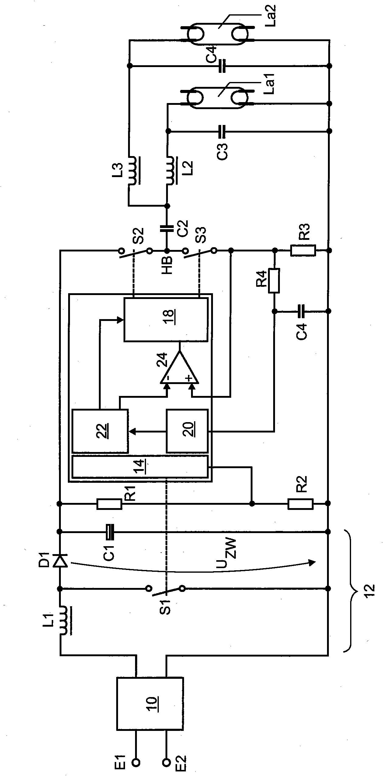
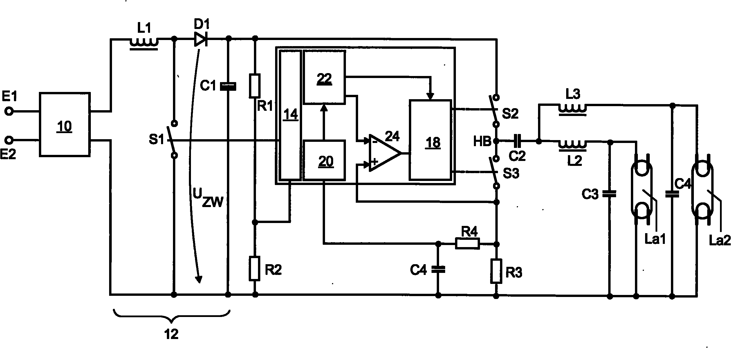
[0017] figure 1 The structure of the electronic ballast for driving the first discharge lamp La1 and the second discharge lamp La2 according to the present invention is schematically shown. On the input side, the ballast comprises a first terminal E1 and a second terminal E2 for connection to the grid voltage U N . This is followed by block 10 which includes the rectifier and components for EMC protection. This is followed by a boost converter 12 comprising an inductor L1, a switch S1, a diode D1 and a capacitor C1. At the output of the boost converter, on the one hand the so-called intermediate circuit voltage U ZW This is supplied to the voltage divider R1 , R2 and on the other hand to the two switches S2 , S3 of the half bridge. The signal tapped off at resistor R2 is fed to unit 14 of microcontroller 16 , unit 14 being used for PFC (power factor correction). For this, in particular switch S1 of boost converter 12 takes into account voltage U sensed by means of resisto...


PUM


Abstract

The invention relates to an electronic ballast for operating at least one first and second discharge lamp, comprising a bridge circuit and inductors connected in series to the respective discharge lamp, a current measuring device (R3), which measures the total current through the first and second inductors, and an actuation circuit for actuating the bridge circuit, a threshold value specificationdevice for specifying a first threshold value for the target value of the total current through the first and second inductors, wherein the electronic ballast furthermore comprises: a starting detection device (20) for detecting whether one of the discharge lamps has started, the threshold value specification device being configured to specify a second threshold value for the target value of the total current through the first and second inductors, the second threshold value being smaller than the first threshold value, and the actuation device being configured to control the bridge circuit while taking the first threshold value into consideration as the target value prior to detecting the starting of a discharge lamp, and while taking the second threshold value into consideration as the target value after detecting the starting of a discharge lamp.

Description

technical field [0001] The invention relates to an electronic ballast for driving at least a first discharge lamp and a second discharge lamp, the electronic ballast: having a bridge circuit comprising at least a first electronic switch and a second electronic switch, wherein the bridge The input of the circuit is coupled to the supply DC voltage, wherein the output of the bridge circuit is coupled to the first terminal of the first discharge lamp and the second terminal of the second discharge lamp, wherein the first terminal and the second terminal are opposite to the bridge circuit The output terminals of the device are connected in parallel; at least a first ignition device and a second ignition device are provided, which respectively include an inductor arranged in series with the corresponding discharge lamp and a capacitor arranged in parallel with the corresponding discharge lamp; and a current measuring device, which is designed as providing at its output a signal ass...

Claims


Application Information

Patent Timeline
Patent Type & Authority Applications(China)
IPC IPC(8): H05B41/285H05B41/38
CPCH05B41/382H05B41/2856
Inventor 奥拉夫·布塞西格弗里德·迈尔阿尔韦德·斯托姆
Owner OSRAM GMBH
Why Eureka
Try Eureka