Moving die compressive stress decomposing and forming method, volume spring and U-shaped bolt composite bending die

A technology of compressive stress and forming method, applied in the direction of springs, springs/shock absorbers, spring components composed of several springs, etc., can solve the problems of small one-time forming load, large volume, and difficult bending/compounding of forging blanks. , to achieve the effect of low maintenance cost, simple structure and convenient manufacturing

Inactive Publication Date: 2010-10-13
李义
View PDF6 Cites 24 Cited by
  • Summary
  • Abstract
  • Description
  • Claims
  • Application Information

AI Technical Summary

Problems solved by technology

[0004] The purpose of the present invention is to solve the problem that the existing forming method under cold pressing is difficult to form the forging blank used for the U-shaped bolt at one time and the problem that the existing compression spring has a small load / large volume and the mold is not easy to bend / composite, and proposes a technical solution One is to provide a dynamic mold compression stress decomposition forming method, the other is to provide a volume spring, and the third is to provide a U-shaped bolt composite bending die

Method used


Image

  • Moving die compressive stress decomposing and forming method, volume spring and U-shaped bolt composite bending die
  • Moving die compressive stress decomposing and forming method, volume spring and U-shaped bolt composite bending die
  • Moving die compressive stress decomposing and forming method, volume spring and U-shaped bolt composite bending die

Examples


Embodiment Construction

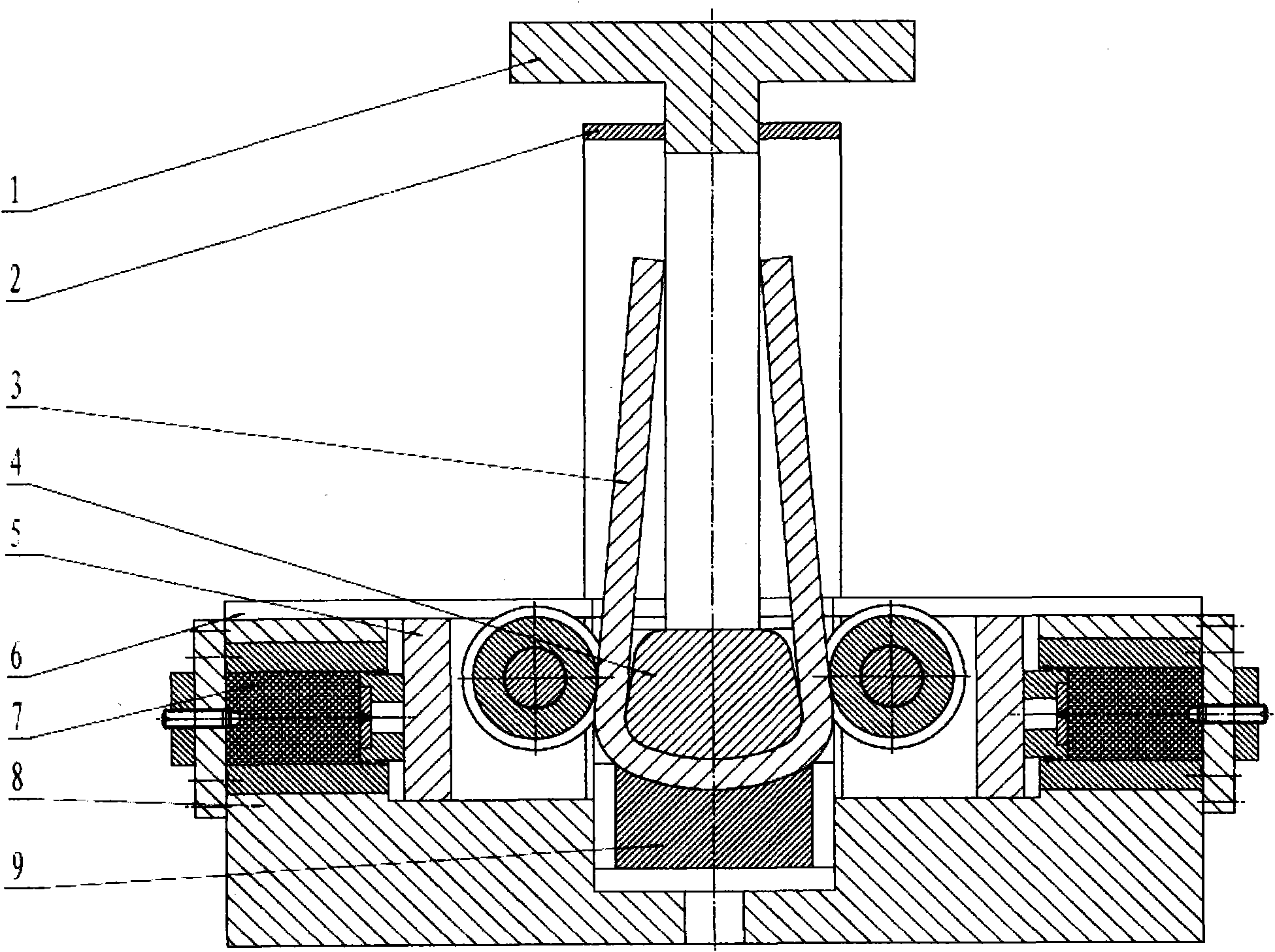
[0024] From attached figure 1 It can be seen that the mold is mainly composed of an upper mold and a lower mold bounded by U-shaped bolts 3 and a rigid unloader connecting them.

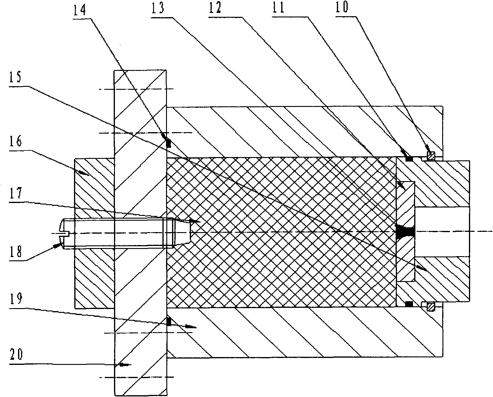
[0025] The material plate is composed of 2, the upper mold is the punch 4 and the punch base 1 is fixedly connected, the lower mold is the movable die 5 with the movable die base 8 as the assembly base, the single-head volume spring 7, the pressure plate 9, and the guide plate 6 composition. attached figure 2 The spring shown is a single-head volume spring 7, the case cover 20 is movably connected with the pressure regulating bolt 18 and the back nut 16, the outer shell 19 and the case cover 20 are fixedly connected with a sealing ring b14, and the rubber 17 is put into the case Insert the sealing ring a12 into the outer wall of the plunger head 15 in the containing cavity of the body 19, insert the air release plug 13 into the pressure insurance block 12 and insert the plunger head 15 into the gu...


PUM


Abstract

The invention relates to a moving die compressive stress decomposing and forming method, a volume spring and a U-shaped bolt composite bending die. Aiming at the problems that under cold pressing, with the 1-2mm large tolerance range of the forging stock thickness of a U-shaped bolt, the rebound of the U-shaped bolt can not be finished in an one-step forming way when a clearance between a convex die and a concave die of a bending die is large, and the die is easy to crush and break open when the clearance is small, and the production efficiency is low, accordingly, a forming die structure of the convex die and the moving concave die under a required clearance state that the clearance between the convex die and the concave die is 1-5 less than the foraging stock thickness is adopted, wherein the convex die is an original rigid-fixed convex die; the moving concave die is a dynamic compressive stress retractable concave die which is formed in such a way that an original concave die is correspondingly separated and guided to limit connection and then is in retractable connection with the volume spring fixedly arranged at the outer side; the volume spring realizes the rebound by compressing the volume of fluid and solid contained and sealed by a metal shell; and the U-shaped bolt composite bending die is obtained by adopting the structure of the convex die and the moving concave die as well as the application of the volume spring, therefore, the aim of controlling rebound bending by the spring is achieved by adopting one-step bending forming compounding with hardness and softness.

Description

[0001] Field [0002] The present invention mainly relates to a forming method in the field of stamping, a compression spring and a bending die, in particular to a controllable dynamic molding stress gapless decomposition forming method and a volume spring with large load and small volume with adjustable pressure And a compound bending die with adjustable springback of U-shaped bolts. Due to its large load and small size, volume springs can also be used as shock-absorbing springs in industries such as machinery, equipment, vehicles, bridges, and construction. Background technique [0003] At present, in the field of stamping, for stamping and bending products, springback is a common phenomenon in bending forming, and it is also a difficult problem that is not easy to solve in the production of bending parts. This point has a solution to springback bending forming in all professional books about stamping technology and die design, especially for U-shaped bending. Due to the ...

Claims


Application Information

Patent Timeline
Patent Type & Authority Applications(China)
IPC IPC(8): B21D37/10F16F3/00
Inventor 李义
Owner 李义
Why Eureka
Try Eureka