Method for manufacturing composite screws

A manufacturing method and screw technology, which is applied in the field of manufacturing composite screws, can solve problems such as inability to improve screw torsional strength, insufficient strength, and poor bonding density.

Inactive Publication Date: 2010-10-13
JOKER IND CO LTD
View PDF7 Cites 0 Cited by
  • Summary
  • Abstract
  • Description
  • Claims
  • Application Information

AI Technical Summary

Problems solved by technology

[0003] With reference to the above-mentioned existing previous cases, it can be learned that most of the joints of the screw segments have insufficient strength or poor bonding density. For example, in the case of the Taiwan TWI306046 patent case, because the locking block is triangular in shape, it makes the teeth rubbing When forming, the cross section of the joint part is not uniformly covered. The acute angle of the triangle is formed after the tooth is rubbed. Because the surrounding screw part is thinner, it turns into the weakest part of the strength. Therefore, this structure The torsional strength of the screw cannot be improved at all; moreover, the manufacturing method in this case includes: material preparation steps, joining steps, tooth rubbing forming steps, and heat treatment steps. The groove structure is the fit of a polygonal plane, and after the joint step presents a tight fit state, it is then extruded and rubbed to form, because the locking block and the groove have a tight fit structure; therefore, in the rubbing The excess material in the tooth forming process can only be extended to the outside, but cannot be deeply combined inside, so that the screw made of it is not very solid in density, resulting in no effective improvement in torsional strength.

Method used


Image

  • Method for manufacturing composite screws
  • Method for manufacturing composite screws
  • Method for manufacturing composite screws

Examples


Embodiment Construction

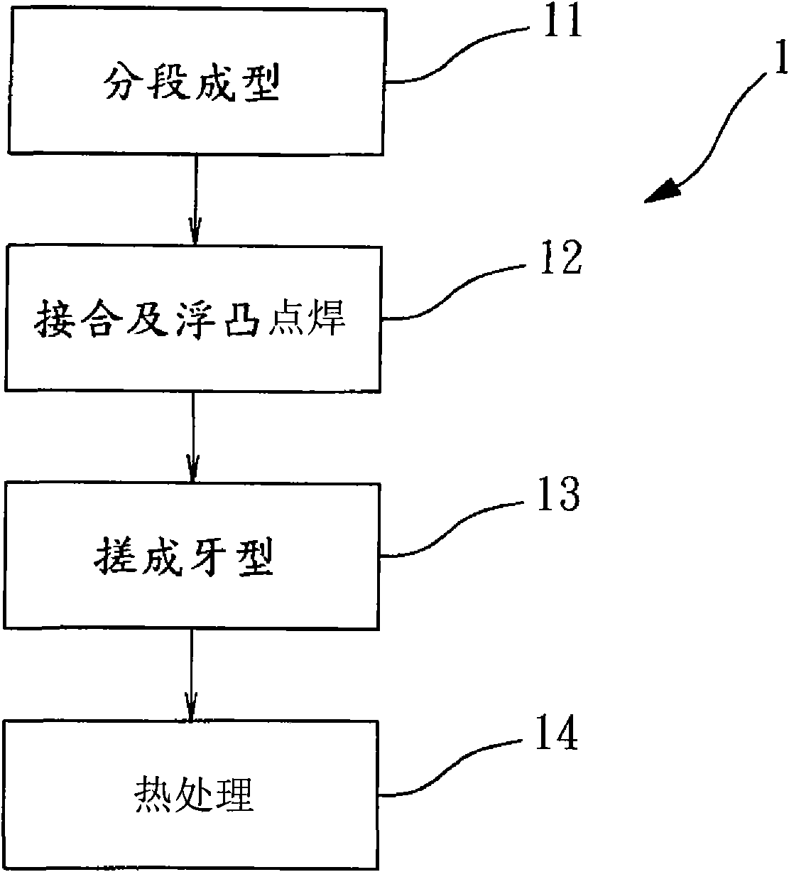
[0025] see figure 1 Shown, manufacturing method 1 of the present invention, it comprises the following steps at least:

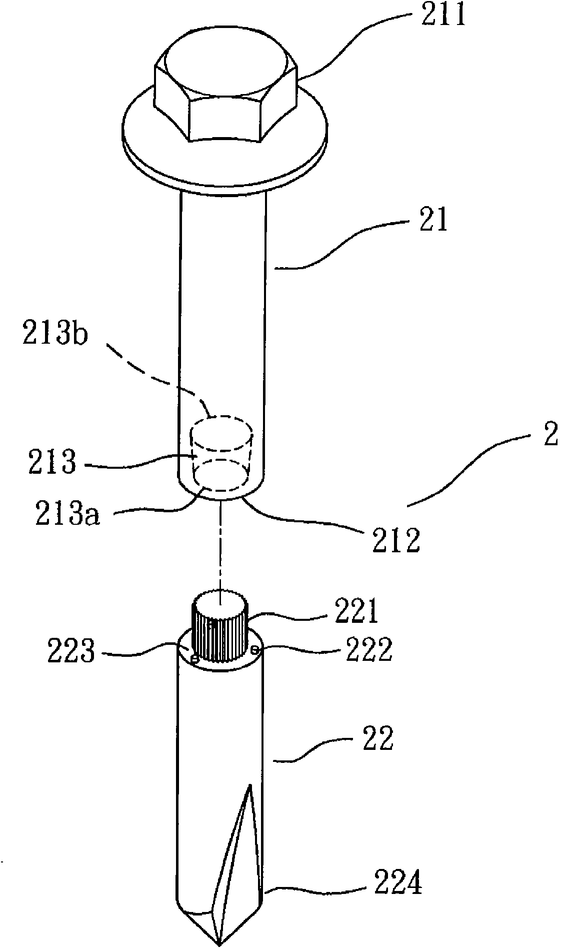
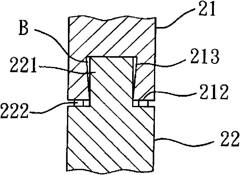
[0026] (1) Sectional molding (step 11), which is to divide the screw 2 sections of different materials into a screw rod part 21 and a drill tail part 22 (please also refer to figure 2 ), which is formed in sections, one end of the screw part 21 forms a nut head 211, and the other end surface 212 has a circular tapered hole 213, and the diameter of the opening 213a of the circular tapered hole 213 is It is smaller than the diameter of the bottom 213b of the circular tapered hole 213, so that the circular tapered hole 213 has a taper, and one end of the drill tail part 22 forms a ratchet-shaped fitting column 221, and the fitting column 221 is formed in the described fitting On the end surface 223 of the outer peripheral edge of the root of the combined column 221, there are a plurality of embossed points 222, and the other end of the drill tail 22 is formed...


PUM


Abstract

The invention relates to a method for manufacturing composite screws, in particular to a method for manufacturing screws which are compounded and made from different materials. The method at least comprises the following steps of: firstly, sectionally forming; secondly, joining and carrying spot welding on embosses; thirdly, kneading into a tooth type; and fourthly, thermally treating. By adopting the steps of the method, the hardness at the rear parts of the screws can be greatly increased and the torsional strength can be enhanced.

Description

technical field [0001] The invention relates to a method for manufacturing a composite screw, especially a method for manufacturing a screw made of composite materials, so as to increase the hardness of the screw tail and improve its torsional strength. Background technique [0002] Screws are widely used in a wide range of applications, especially in the production of fast mass production, but the screw must have sufficient tail drilling capacity and be able to bear the locking torque, so the screw itself should have a considerable hardness And torsional strength, in order to meet the needs of use; however, to achieve sufficient hardness and torsional strength, it is very important to select materials. If a material with high hardness and sufficient torsional strength is selected, the manufacturing cost will be relatively higher. , and will also affect the ability to receive orders and bids. For this reason, the industry has successively introduced a variety of composite sc...

Claims


Application Information

Patent Timeline
Patent Type & Authority Applications(China)
IPC IPC(8): B21H3/06
Inventor 黄邦卿
Owner JOKER IND CO LTD
Why Eureka
Try Eureka