Assembly component and assembly method for crankshaft timing gear

A timing gear and assembly component technology, applied in metal processing, metal processing equipment, manufacturing tools, etc., can solve the problems of difficult pressing, poor assembly stability, low accuracy, etc., to improve assembly stability and accuracy, reduce The effect of pressing difficulty

Active Publication Date: 2010-10-13
GUANGXI YUCHAI MASCH CO LTD
View PDF0 Cites 12 Cited by
  • Summary
  • Abstract
  • Description
  • Claims
  • Application Information

AI Technical Summary

Problems solved by technology

[0009] The purpose of the present invention is to propose a crankshaft timing gear assembly assembly for the defects of high difficulty in press-fitting, poor assembly stability and low precision in the prior art, so as to reduce the difficulty of press-fitting and improve the stability and precision of assembly
[0010] Further, another purpose of the present invention is to propose a crankshaft timing gear assembly method to reduce the difficulty of press-fitting and improve the assembly stability in view of the defects of high difficulty in press-fitting, poor assembly stability and low precision in the prior art sex and precision

Method used


Image

  • Assembly component and assembly method for crankshaft timing gear
  • Assembly component and assembly method for crankshaft timing gear
  • Assembly component and assembly method for crankshaft timing gear

Examples


Embodiment 1

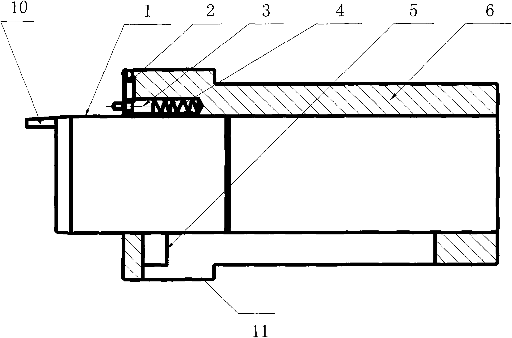
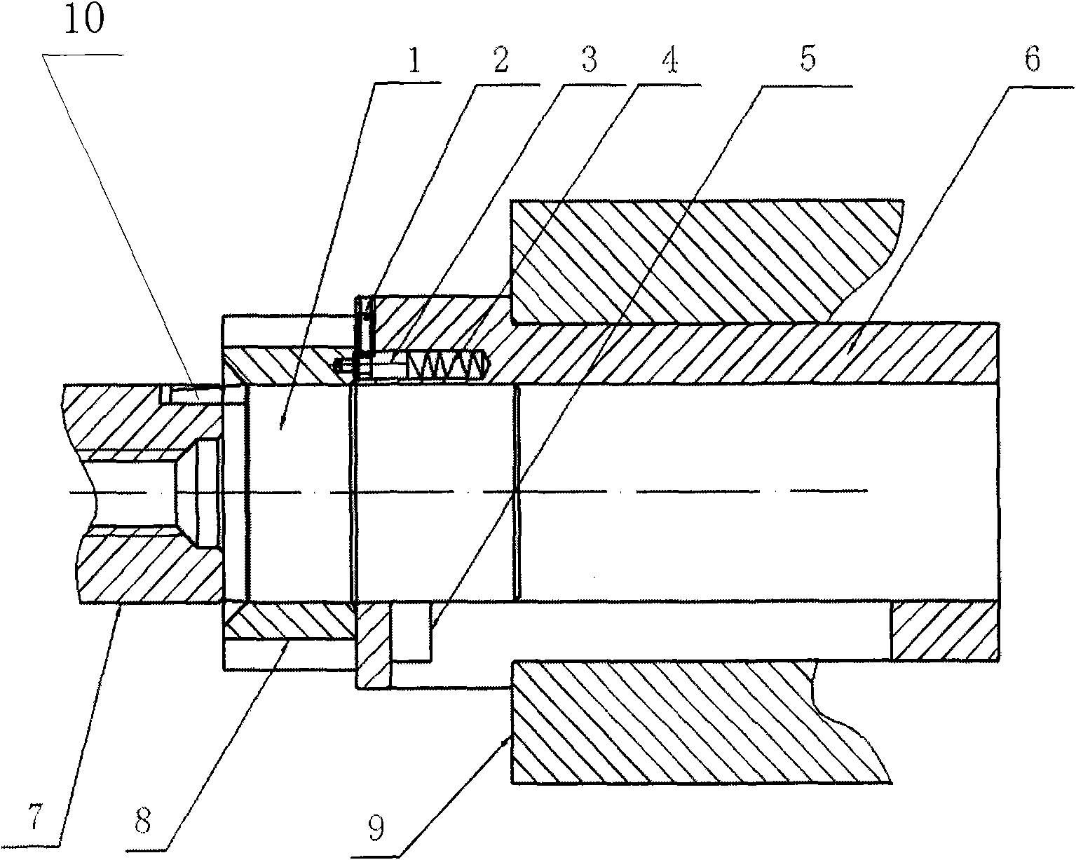
[0032] According to an embodiment of the present invention, a crankshaft timing gear assembly assembly is provided. Such as figure 1 and figure 2 As shown, this embodiment includes a guide shaft 1 and a guide sleeve 6 , wherein the guide sleeve 6 can be axially slidably fitted on the guide shaft 1 .

[0033] In this embodiment, on the guide shaft 1, a positioning key 10 can be provided at the end away from the guide sleeve 6, and the positioning key 10 is located at the bottom of the guide shaft; The pin 5 is located on the side of the guide shaft 1 and is used to limit the relative position between the guide shaft 1 and the guide sleeve 6 . On the guide sleeve 6, a positioning pin 3 may be provided at an end away from the guide shaft 1, and the positioning pin 3 is parallel to the guide shaft 1 and close to the guide shaft 1; a shoulder structure 11 is provided at an end close to the positioning pin 3, The shoulder structure 11 is arranged on the periphery of the guide sl...

Embodiment 2

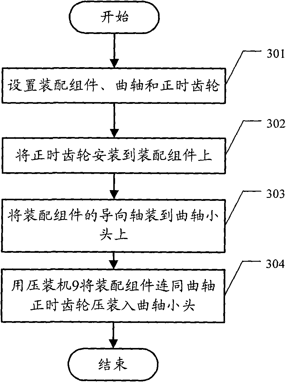
[0038] According to an embodiment of the present invention, a crankshaft timing gear assembly method is provided. Such as Figure 1-Figure 3 As shown, this embodiment includes:

[0039] Step 301: Set the assembly components, and set the crankshaft and timing gear 8 accordingly according to the assembly components; specifically:

[0040]The assembly assembly, that is, the crankshaft timing gear assembly assembly includes a guide shaft 1 and a guide sleeve 6 sleeved on the guide shaft 1 in an axial sliding manner, wherein a raised positioning key is provided at the end of the guide shaft 1 away from the guide sleeve 6 10. The positioning key 10 is located at the bottom of the guide shaft 1. The positioning key 10 can be used to fix the relative position between the assembly assembly and the small end of the crankshaft 7; Position pin 5 can be used to limit the relative position between guide shaft 1 and guide sleeve 6; An end near guide key 10 is provided with guide pin 3 at g...


PUM


Abstract

The invention discloses an assembly component and an assembly method for a crankshaft timing gear. The assembly component comprises a guide shaft and a guide sleeve which is axially and glidingly sleeved on the guide shaft. The method comprises the following steps of: setting the assembly component consisting of the guide shaft and the guide sleeve, and setting a crankshaft and a timing gear according to the assembly component; arranging the timing gear on the guide sleeve of the assembly component; arranging the guide shaft on the small head of the crankshaft; and pressing the assembly component and the crankshaft timing gear into the small head of the crankshaft together by using a press so as to finish the assembly of the crankshaft timing gear. The assembly component and the assembly method can overcome the defects of high pressing difficulty, poor assembly stability, low precision and the like in the prior art to relieve the pressing difficulty and improve the assembly stability and the precision.

Description

technical field [0001] The invention relates to crankshaft timing gear assembly technology, in particular to a crankshaft timing gear assembly assembly and method. Background technique [0002] The assembly requirement between the crankshaft small end and the crankshaft timing gear of the earlier diesel engine is a transition fit, relying on the keyway on the crankshaft small end and the keyway on the crankshaft timing gear to transmit torque through the key. However, there are some defects in this structure, that is, processing a keyway on the relatively small crankshaft head will inevitably cause serious damage to the strength of the crankshaft head, so that the crankshaft head breaks and the like. [0003] At present, in order to overcome the above defects, the assembly between the crankshaft small end and the crankshaft timing gear is generally required to be an interference fit structure, thereby canceling the traditional method of key transmission torque, relying on th...

Claims


Application Information

Patent Timeline
Patent Type & Authority Applications(China)
IPC IPC(8): B23P19/02
Inventor 何江华朱岩农永新黎祖赵刘时国韩光
Owner GUANGXI YUCHAI MASCH CO LTD
Why Eureka
Try Eureka