Vacuum pump motor output shaft installation device

An installation device and output shaft technology, applied in metal processing equipment, metal processing, manufacturing tools, etc., can solve the problems of large shaft runout, scratches on the surface of the output shaft, reducing the pass rate of press fitting, etc. The effect of reducing the probability of beating, reducing production costs, and reducing product costs

Active Publication Date: 2021-01-01
CHONGQING PINGJIANG IND
View PDF5 Cites 0 Cited by
  • Summary
  • Abstract
  • Description
  • Claims
  • Application Information

AI Technical Summary

Problems solved by technology

[0005] 1. Because the lamination 17 must ensure an interference fit with the output shaft after press-fitting, during the press-fitting process, as the length of the lamination 17 is pressed into the output shaft increases, coupled with the interference fit, the output shaft of the lamination 17 contacts The frictional force generated during the process is constantly increasing, which hinders the movement of the lamination 17 relative to the output shaft. At this time, the pressing block of the pressing device is still continuously applying pressure to the lamination 17, and the lamination 17 cannot move relative to the output shaft. As a result, the shaft deformation and shaft runout of the output shaft become larger, which affects the quality of the output shaft, causes the lamination 17 to fail in press-fitting, and reduces the qualified rate of press-fitting
[0006] 2. If the lamination 17 is divided into two parts, the press-fitting is carried out twice to reduce the friction between the lamination 17 and the output shaft during each press-fitting, thereby reducing the axial friction of the output shaft after the lamination 17 is pressed. The probability of deformation and shaft runout becomes larger. However, when the existing device presses the second lamination 17, it cannot guarantee the alignment of the two laminations 17, which leads to the failure of pressing the lamination 17.
[0007] In addition, after the lamination 17 is installed on the output shaft, the output shaft needs to be installed on the vacuum pump motor. During the installation process, the output shaft needs to be fixed on the vacuum pump motor through the mounting seat. In the prior art, generally The mounting base is installed on the motor by hand. The above operation has the following problems: When installing the mounting base on the motor, the operator cannot accurately align the mounting hole on the mounting base with the output shaft. There will be a large friction between the wall of the installation hole of the seat and the output shaft, and scratches will be generated on the surface of the output shaft, which will cause damage to the output shaft and need to be replaced

Method used


Image

  • Vacuum pump motor output shaft installation device
  • Vacuum pump motor output shaft installation device
  • Vacuum pump motor output shaft installation device

Examples


Embodiment 1

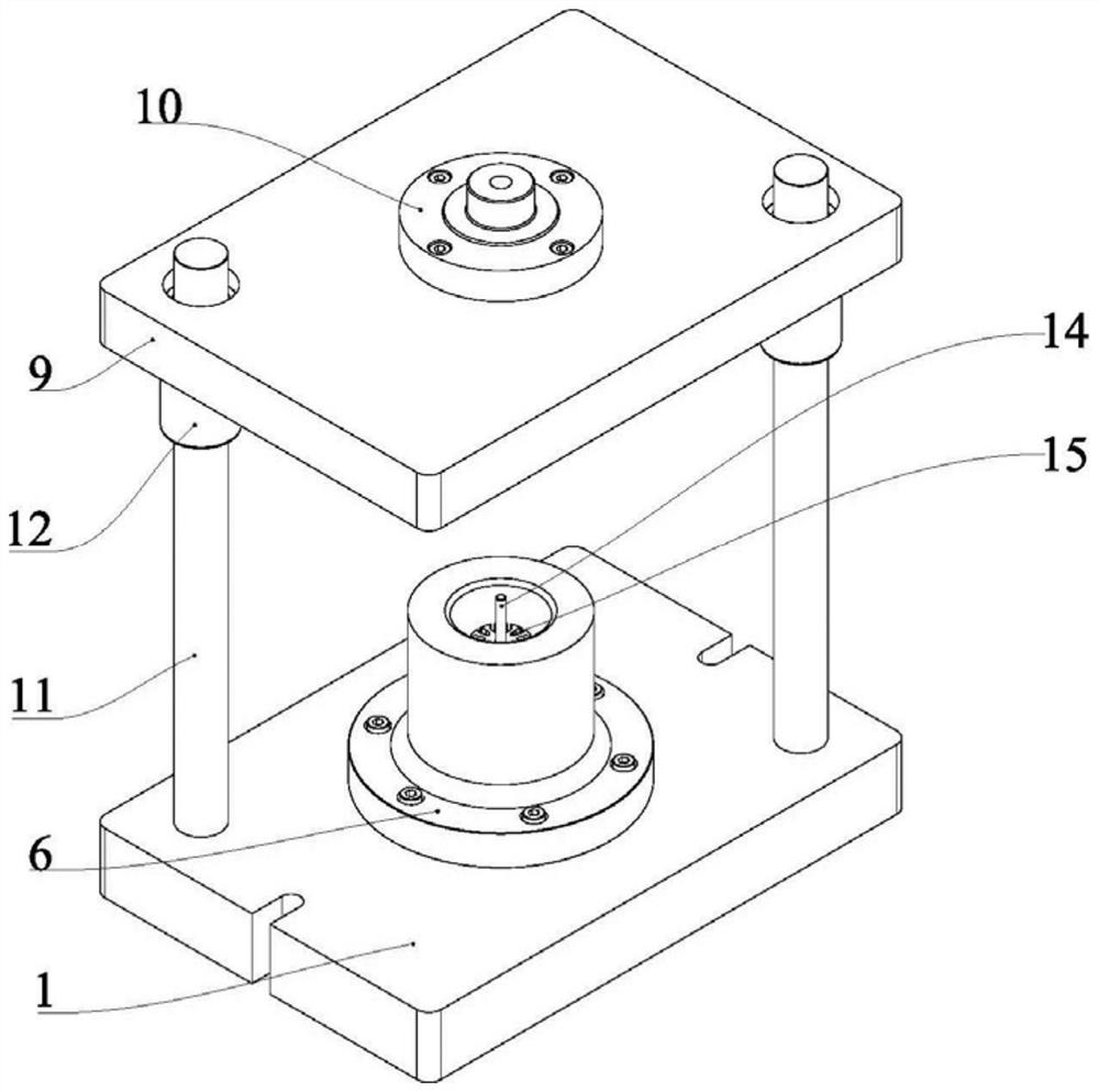
[0031] Embodiment one is basically as Figure 2 to Figure 5 Shown: combined Figure 3 to Figure 4 , the vacuum pump motor output shaft installation device, including the lower mold base 1, the flange plate 6, the guide post 11, the guide sleeve 12, the upper mold base 9, the floating mold handle 10 and the pressure head 7, and the flange plate 6 is fixedly connected to the lower mold base 1, the guide post 11 connects the upper die base 9 and the lower die base 1, the upper die base 9 can move up and down along the guide post 11, the guide sleeve 12 fits on the guide post 11, and the guide sleeve 12 is located between the upper die base 9 and the lower die base 1. Between the lower mold bases 1 , the lower surface of the upper mold base 9 is fixedly connected with the indenter 7 , and the upper surface of the upper mold base 9 is connected with the floating mold handle 10 .

[0032] combine Figure 5 , the flange 6 is provided with a cavity for lamination forming, the pressu...

Embodiment 2

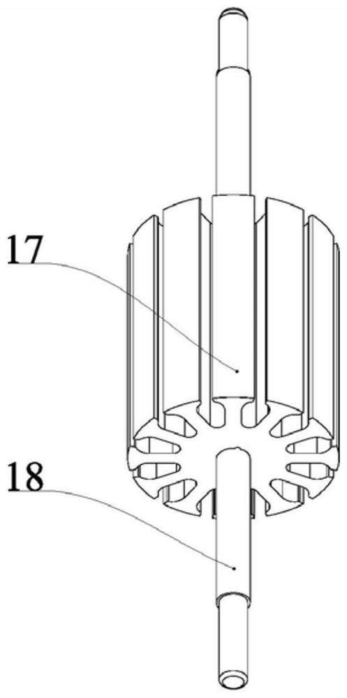
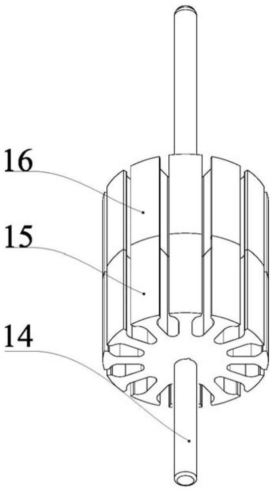
[0040] Embodiment two is basically as Image 6 As shown: Embodiment 2 is based on Embodiment 1. The difference is that the shaft mounting seat 5 is slidably connected in the cavity of the flange 6, and the ejector rod 19, the first wedge rod 20, and the second wedge rod 21 are added. And the third wedge bar 22.

[0041] The ejector rod 19 is fixedly connected to the bottom of the upper die base 9, and a cavity is opened in the lower die base 1, and the first wedge rod 20, the second wedge rod 21 and the third wedge rod 22 are slidably connected in the cavity, and the ejector rod 19 is used for When the first wedge rod 20 is pushed, the first wedge rod 20 meshes with the second wedge rod 21, the left side of the second wedge rod 21 meshes with the third wedge rod 22, and the top end of the third wedge rod 22 abuts against the plug 3, A first spring is connected between the first wedge rod 20 and the cavity wall, and a second spring is connected between the second wedge rod 21 ...

Embodiment 3

[0043] Embodiment three such as Image 6 As shown: Embodiment 3 is based on Embodiment 2. The difference is that the coaxial installation mechanism of the mounting seat 28 includes a sliding seat 23 installed on the frame, and the sliding seat 23 is fixedly connected with a support rod 26. Have threaded hole, threaded hole internal thread is connected with locating rod 29, is also slidably connected with motor 32 mounting table 31 on the frame, has the positioning hole for locating rod 29 insertion in the motor 32 mounting table 31, and slide seat 23 inner rotation Connected with driving screw rod 25, on the support rod 26 slidingly connected with positioning frame 27, driving screw rod 25 is threadedly connected with positioning frame 27, is fixedly connected with the first cylinder 33 and the second cylinder 34 on the frame, the output shaft of the first cylinder 33 14 is fixedly connected with the sliding seat 23, and the output shaft 14 of the second air cylinder 34 is fix...


PUM


Abstract

The invention relates to the technical field of motor machining, in particular to a mounting device of an output shaft of a vacuum pump motor. The mounting device comprises a rack; and a lamination alignment type press-fitting mechanism and a mounting seat coaxial mounting mechanism are mounted on the rack. according to the scheme, in order to solve the problems that the quality of the output shaft is affected, the percent of pass of press-fitting is reduced, relatively large friction can be produced between the mounting seat and the output shaft and scratches can be produced on the surface ofthe output shaft after lamination press-fitting in the prior art, the lamination alignment type press-fitting mechanism is arranged, so that the press-fitting difficulty is greatly reduced, the probability of shaft deformation and shaft jumping of the output shaft is further reduced, and the yield of press-fitting is increased; a polished shaft is used as the output shaft and is not required to be machined into a stepped shaft, and then the product cost is reduced; and the mounting seat coaxial mounting mechanism is arranged, so that scratches can be prevented from being produced on the output shaft, and damage to the output shaft is prevented.

Description

technical field [0001] The invention relates to the technical field of motor processing, and specifically discloses a vacuum pump motor output shaft installation device. Background technique [0002] The middle section of the output shaft of the vacuum pump motor is connected with laminations 17, and the two ends of the output shaft are connected with other parts through bearings. The output shaft in the prior art is a stepped shaft 18 (as figure 1 shown), the lamination 17 needs to be press-fitted into the stepped shaft 18 by a press-fitting device; the press-fitting device of the lamination 17 includes an upper mold base, a lower mold base, a guide post and a guide sleeve, and the guide post connects the upper die base and the The lower die base, the upper die base can move up and down along the guide post, the guide sleeve fits on the guide post, the guide sleeve is located between the upper die base and the lower die base, and the lower die base is provided with a moldi...

Claims


Application Information

Patent Timeline
Patent Type & Authority Patents(China)
IPC IPC(8): B23P19/027
CPCB23P19/027
Inventor 姜秋玲赵宇江玲玲谭平严文
Owner CHONGQING PINGJIANG IND
Why Eureka
Try Eureka