
LED ceiling lamp

A technology of LED ceiling lamps and lamps, which is applied in the direction of lampshades, lighting and heating equipment, semiconductor devices of light-emitting elements, etc., can solve the problems of LED ceiling lamps, large ceiling space, and poor energy saving, etc., to save ceiling space, The effect of reducing the hanging height and reducing the volume

Inactive Publication Date: 2010-10-13
深圳市兴皓地电子有限公司
View PDF4 Cites 8 Cited by
  • Summary
  • Abstract
  • Description
  • Claims
  • Application Information

AI Technical Summary

Problems solved by technology

[0002] Downlight is a traditional ceiling lamp, which mainly uses halogen lamps or energy-saving lamps as the light source. The existing ceiling downlight has a large size and a large volume when it penetrates into the ceiling, so it occupies a large space in the ceiling, and its quality Heavy, poor energy efficiency
With the development of science and technology, LED as a lamp has many advantages such as energy saving and environmental protection, and is being used more and more widely in lamps, but there is no LED ceiling lamp that can directly replace the existing ceiling downlight.

Method used


Image

  • LED ceiling lamp
  • LED ceiling lamp
  • LED ceiling lamp

Examples


Embodiment Construction

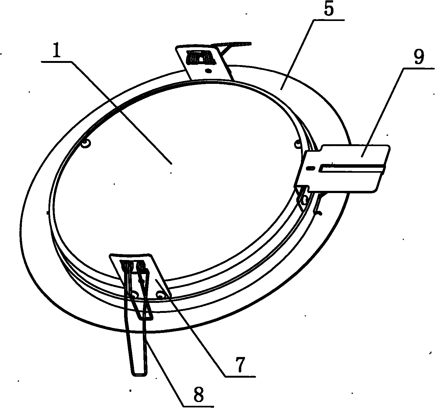
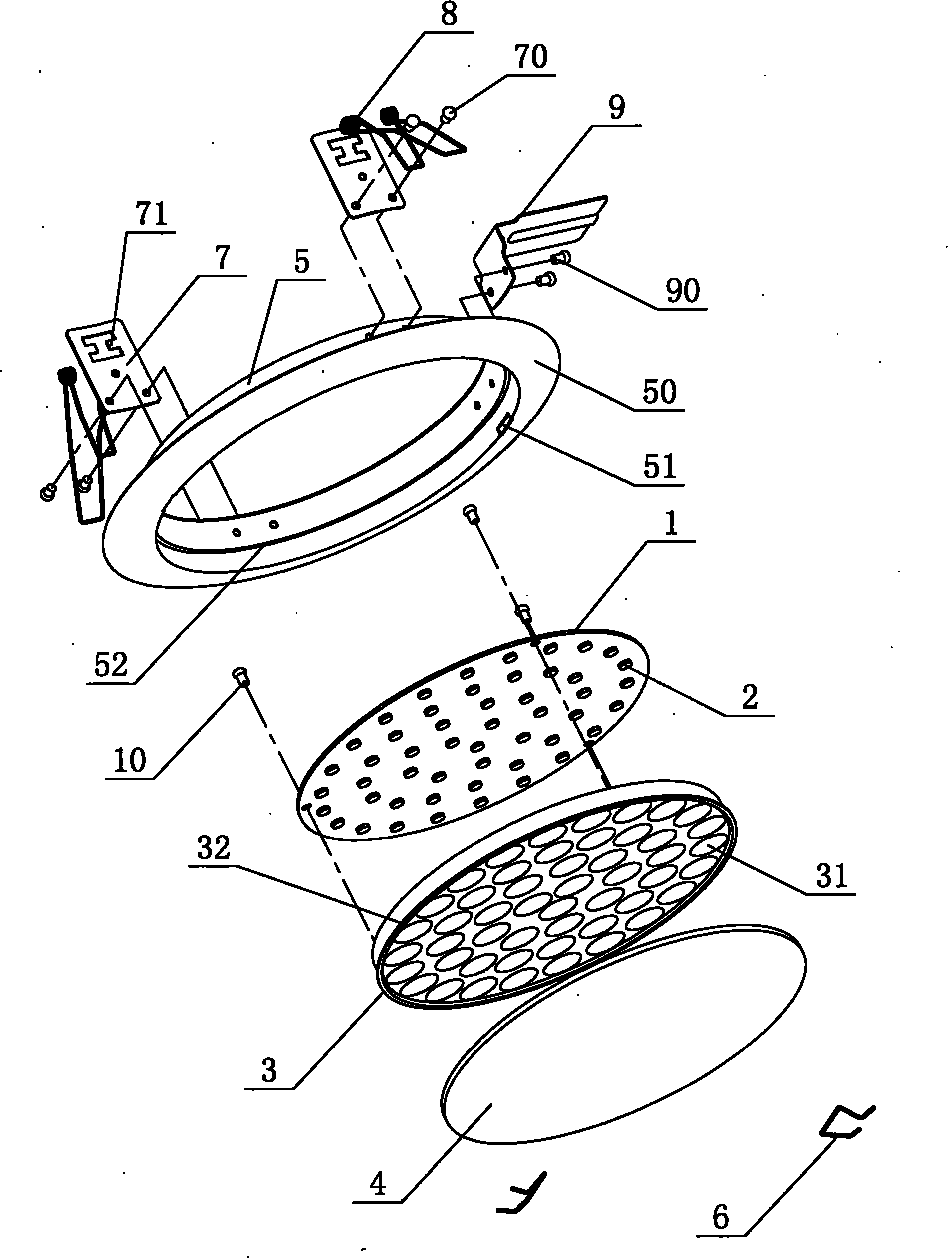
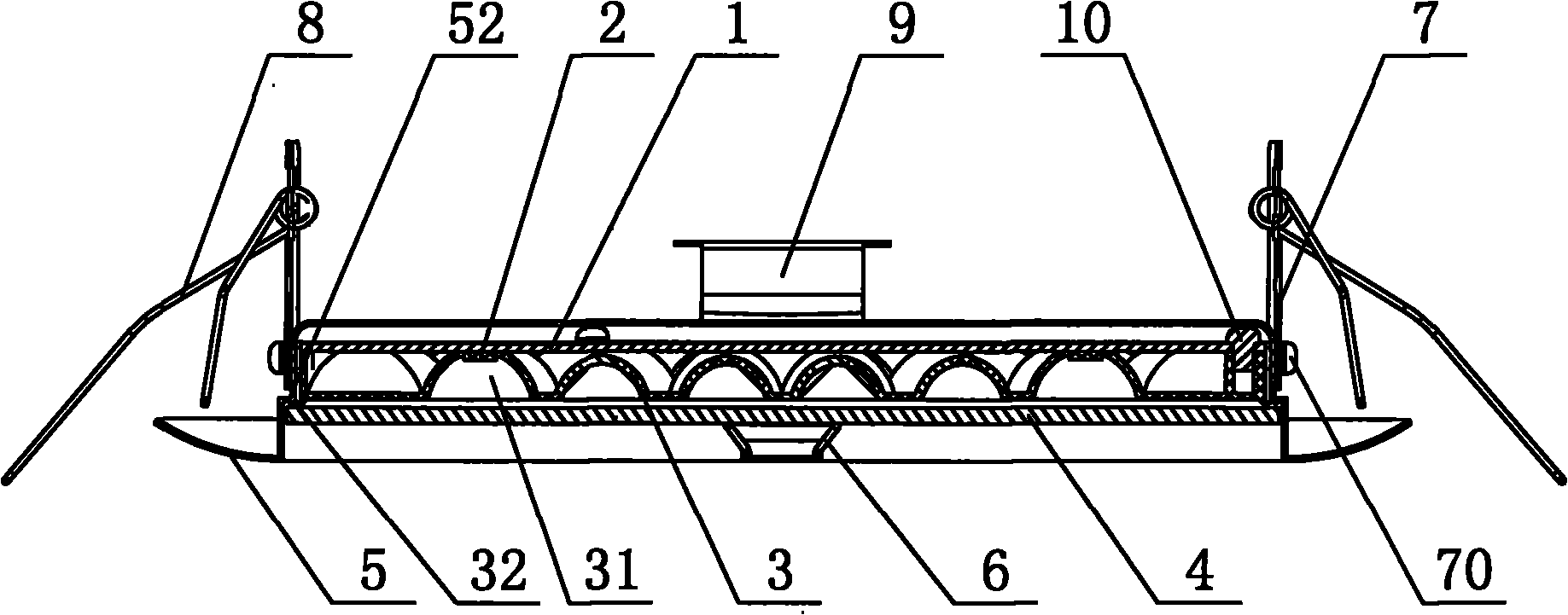
[0018] Such as Figure 1 ~ Figure 4 As shown, the LED ceiling lamp of this embodiment can be used to replace existing ceiling downlights, including an LED circuit substrate 1, a light distribution plate 3, a light-transmitting surface cover 4, a lamp frame 5, two surface cover circlips 6, two Two spring brackets 7, two mounting springs 8, and a power supply bracket 9. The LED circuit substrate 1 adopts a double-sided copper-clad plate. Of course, metal substrates such as aluminum substrates can also be used. The LED circuit substrate 1 is provided with several LEDs 2 , The light distribution plate 3 is provided with a number of light reflection grooves 31, the LED circuit substrate 1 and the light distribution plate 3 are fixedly connected by screws 10, of course, other fixing methods can also be used, the light reflection grooves 31 and the The positions of the LEDs 2 correspond one-to-one. The light-transmitting surface cover 4 is located on the front of the light distributio...


PUM


Abstract

The invention discloses an LED ceiling lamp with advantages of small volume, light mass, saving of ceiling space, low temperature rise, energy conservation, environmental protection, high light efficiency and capability of replacing the conventional ceiling tube lamp. The LED ceiling lamp comprises an LED circuit substrate (1), a light distribution plate (3), a light transmission front cover (4), a lamp framework (5), a front cover clamp spring (6), a spring bracket (7), a mounting spring (8) and a power supply bracket (9), wherein an LED (2) is arranged on the LED circuit substrate (1); a reflection groove (31) is formed on the light distribution plate (3); the LED circuit substrate (1) is fixedly connected with the light distribution plate (3); the reflection groove (31) corresponds to the position of the LED (2); the light transmission front cover (4) is positioned on the front of the light distribution plate (3); the light transmission front cover (4) is fastened on the lamp framework (5) through the front cover clamp spring (6) and presses the LED circuit substrate (1) and the light distribution plate (3) to be fixed; the spring bracket (7) and the power supply bracket (9) are fixed on the lamp framework (5); the mounting spring (8) is connected with the spring bracket (7); and the front of the lamp framework (5) is provided with an annular face ring (50).

Description

Technical field [0001] The invention relates to an LED ceiling lamp. Background technique [0002] Downlight is a traditional ceiling light, which mainly uses halogen lamp or energy-saving lamp as the light source. The existing ceiling downlight has a large size and volume deep into the ceiling, so it occupies a large space and quality. Heavy and poor energy saving. With the development of science and technology, LED as a lamp has many advantages such as energy saving and environmental protection, and it is being used more and more widely in lamps. However, there is no LED ceiling lamp that can directly replace the existing ceiling downlight. . Summary of the invention [0003] The technical problem to be solved by the present invention is to overcome the shortcomings of the prior art, and provide an LED that is small in size, light in weight, saves ceiling space, small temperature rise, energy saving, environmental protection, high luminous efficiency, and can replace the exist...

Claims


Application Information

Patent Timeline
Patent Type & Authority Applications(China)
IPC IPC(8): F21S4/00F21V17/00F21V3/00F21V21/00F21K9/20F21V3/04F21Y115/10
Inventor 蒋群力
Owner 深圳市兴皓地电子有限公司
Learn More