Tube-in-tube illuminating lamp adopting cold cathode lamp tube

A cold cathode and tube-in-tube technology, which is applied to lighting devices, lighting and heating equipment, and parts of lighting devices. No problem, achieve the effect of no damage, automatic optimization of lamp parameters, and low maintenance cost

Inactive Publication Date: 2010-10-13
YICHANG JINSEN OPTRONICS TECH +1
4 Cites 5 Cited by

AI-Extracted Technical Summary

Problems solved by technology

[0002] Traditional T5/T8 and other fluorescent lamps, as a grille lighting and decorative backlight, have disadvantages such as high power consumption, short life, fast light decay, about 3000H attenuation of 50%, and low switching times of about 100,000 times.
Long-term lighting and many times of switching will lead to premature aging of the lamp tube; severe stroboscopic, it takes a few seconds to flicker when it is turned on, and after several months of lighting, the brightn...

Method used

4) T5/T8 fluorescent lamp needs external electronic rectifier, adopts the tube-in-tube illuminating lamp of cold cathode lamp tube to adopt integrated type, cold cathode lamp tube 6 and lamp tube driving inverter 5 are combined in outer ...

Abstract

The invention discloses a tube-in-tube illuminating lamp adopting a cold cathode lamp tube, relating to an illuminating lamp. An outer tube is internally provided with a reflector, the cold cathode lamp tube is arranged on a working side of the reflector through a tube clamp, the other side of the reflector is provided with an inverter, the inverter is in electric connection with an output end of the cold cathode lamp tube, and electrodes at the input end of the inverter is lead out to the two ends of the outer tube through a lamp holder, wherein the outer tube is made by T5/T8 specification. The invention can sufficiently utilize the connection of a traditional lamp carrier of the T5/T8 specification, has long service life, low maintenance cost and good light directivity, and is very suitable for illumination in places, such as offices, schools, commercial centers and the like.

Application Domain

Technology Topic

Image

  • Tube-in-tube illuminating lamp adopting cold cathode lamp tube
  • Tube-in-tube illuminating lamp adopting cold cathode lamp tube
  • Tube-in-tube illuminating lamp adopting cold cathode lamp tube

Examples

  • Experimental program(1)

Example Embodiment

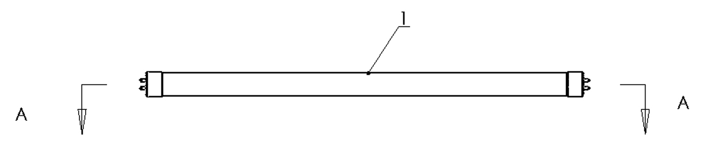
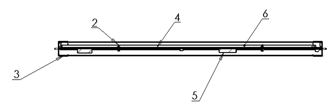
[0014] A tube-in-tube lighting lamp using a cold-cathode lamp tube, the outer tube 1 is provided with a reflector 4, the cold-cathode lamp 6 is installed on the working side of the reflector 4 through the tube clip 2, and the other side of the reflector 4 is installed. There is an inverter 5 , the inverter 5 is electrically connected to the output end of the cold cathode lamp 6 , and the electrodes of the input end of the inverter 5 are led out to both ends of the outer tube 1 through the lamp cap 3 . The outer tube adopts T5/T8 specification. In this way, the existing lamp holder of T5/T8 specification can be used, and it can be directly clipped on the existing lamp holder, so that the cost can be saved. The working side of the reflective sheet 4 referred to here is the reflective side of the reflective sheet.
[0015] The cold cathode lamp tube 6 is U-shaped or straight tube type, and the length is 500-1200mm.
[0016] The diameter of the cold cathode lamp tube 6 is 2.4-8.0 mm.
[0017] The control circuit of the inverter 5 adopts an intelligent IC half-bridge driving chip. For example model: FAN7711.
[0018] The connection between the inverter 5 and the cold cathode lamp 6 is double-ended reversed-phase high-voltage driving.
[0019] Compared with the T5/T8 fluorescent lamp test, the U-shaped cold-cathode tube-in-tube lighting lamp of the present invention, taking a 550mm long tube-in-tube lamp as an example, has the following advantages:
[0020] 1) The power consumption of a T5/T8 fluorescent lamp is between 20-30W, and the power consumption of a tube-in-tube lamp using a cold cathode lamp is between 14-16W;
[0021] 2) The luminous flux of a T5/T8 fluorescent lamp is 1100-1300lm, and the luminous flux of the tube-in-tube lighting using cold cathode lamps is 1000-1100lm, and the luminous flux is increased by 50% compared with the same input power.
[0022] 3) The average service life of T5/T8 fluorescent tube wall is 6000 hours, the efficiency of electronic rectifier is 85%, the service life of tube-in-tube lighting using cold cathode tube is more than 50000 hours, the efficiency of inverter 5 is more than 90%, More energy saving and environmental protection.
[0023] 4) T5/T8 fluorescent lamps need an external electronic rectifier, and the tube-in-tube lighting using cold cathode lamps adopts an integrated type. The cold cathode lamp 6 and the lamp drive inverter 5 are combined in the outer tube 1 to reduce the three-dimensional space. Occupied, and the outer tube 1 adopts the T5/T8 specification. Therefore, the existing T5/T8 matching lamp sockets can be used, which is easy to install and has good light directivity.
[0024] The above description of one embodiment of the present invention is intended to facilitate the understanding and understanding of the new type of the present invention, and those skilled in the art can also make various changes and modifications without departing from the scope of the appended claims of the present invention. Improvements, such as: changing the shape of the lamp tube to a straight tube type, changing the size of the lamp tube, etc. However, such transformations and improvements belong to the scope of the present invention.

PUM

PropertyMeasurementUnit
Diameter2.4 ~ 8.0mm
tensileMPa
Particle sizePa
strength10

Description & Claims & Application Information

We can also present the details of the Description, Claims and Application information to help users get a comprehensive understanding of the technical details of the patent, such as background art, summary of invention, brief description of drawings, description of embodiments, and other original content. On the other hand, users can also determine the specific scope of protection of the technology through the list of claims; as well as understand the changes in the life cycle of the technology with the presentation of the patent timeline. Login to view more.

Similar technology patents

Thermochromic aluminum silicate glass and preparation method thereof

InactiveCN108558203AGood color renderingFast color change response timeAlkali metalAluminum element
Owner:(CNBM) BENGBU DESIGN & RES INST FOR GLASS IND CO LTD

Semiconductor Illuminating Device

ActiveUS20180033921A1Good color renderingGood color saturationSolid-state devicesLuminescent compositionsColor temperatureRadiation
Owner:OSRAM OLED

Classification and recommendation of technical efficacy words

  • Good color rendering
  • Reduce maintenance costs

Red double-perovskite fluorescent powder for white-light LEDs and preparation method of red double-perovskite fluorescent powder

ActiveCN102634340AGood color renderingHigh emission intensityGas discharge lamp usageLuminescent compositionsRare-earth elementIon
Owner:武汉视美乐激光显示发展有限公司

Fluorescent material with molybdate and tungstate as matrixes as well as preparation method and application thereof

InactiveCN102199427AHigh emission intensityGood color renderingGas discharge lamp usageLuminescent compositionsYttriumTungstate
Owner:JINAN UNIVERSITY
Why Eureka
Try Eureka