Control method of equipment containing pressure sensor

A pressure sensor and control method technology, applied in mechanical pressure/force control, electrical program control, non-electric variable control, etc., can solve problems such as unfavorable pressure sensor application, cumbersome, complex and other problems

Active Publication Date: 2010-10-13
鸣志精密制造(太仓)有限公司
View PDF0 Cites 2 Cited by
  • Summary
  • Abstract
  • Description
  • Claims
  • Application Information

AI Technical Summary

Problems solved by technology

[0014] Since the frequency signals used for programming in the control part of the equipment are compiled using standard, fixed frequency signal curves, when a frequency signal falls on the standard frequency signal curve, the control part knows what the pressure sensor is now state, and then issue instructions to control the corresponding components to operate; however, the frequency signal curves generated by different pressure sensors are also different, or higher than the standard frequency signal curve, or lower than the standard frequency signal curve, therefore, in After the pressure sensor is installed, the frequency signal curve of the pressure sensor must be manually adjusted to coincide with the standard frequency signal curve, so that the control part can operate and control the corresponding components according to the standard frequency signal curve, which is very complicated and cumbersome. , it is also not conducive to the application of the same type of pressure sensor to different devices

Method used


Image

  • Control method of equipment containing pressure sensor
  • Control method of equipment containing pressure sensor
  • Control method of equipment containing pressure sensor

Examples


Embodiment 1

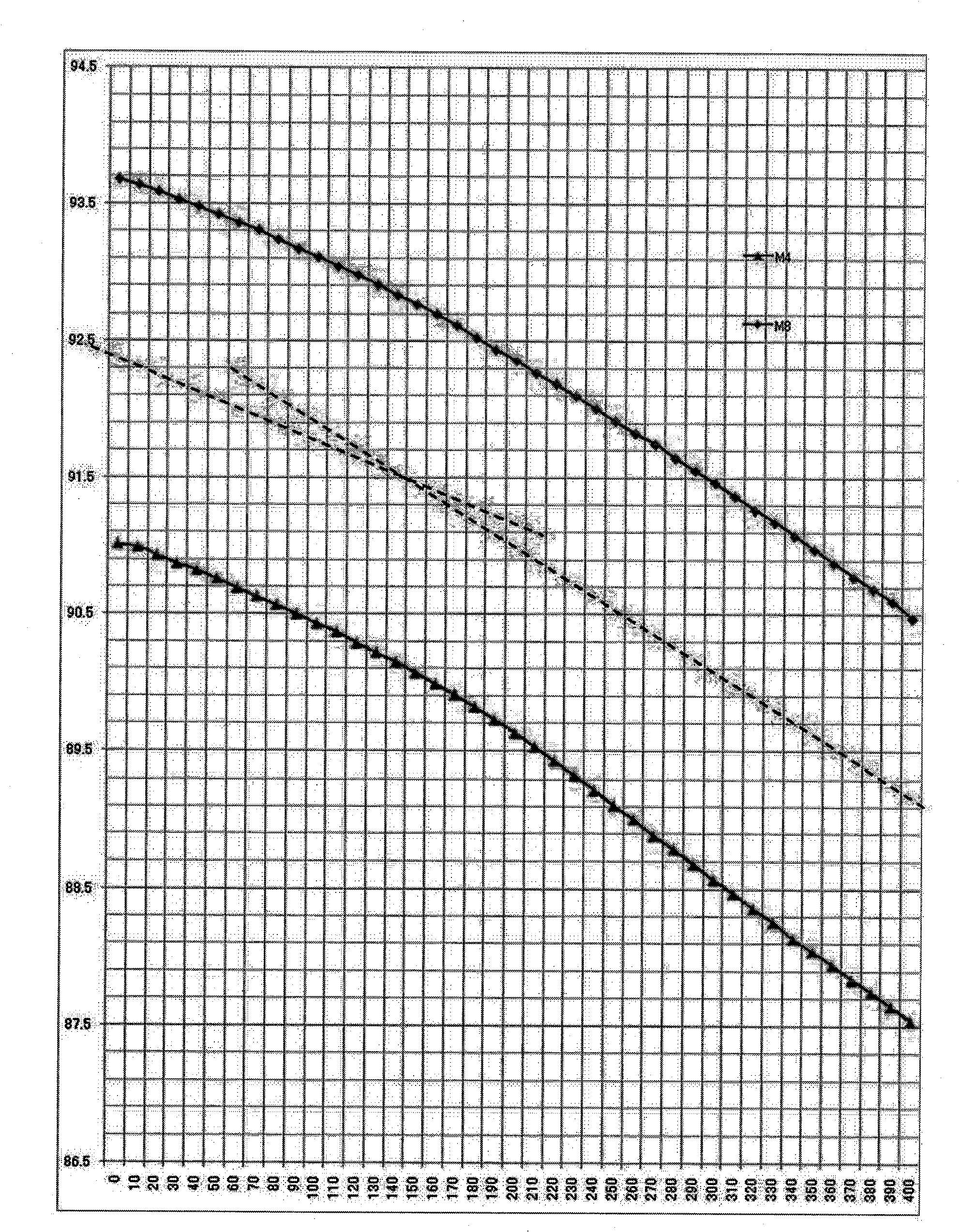
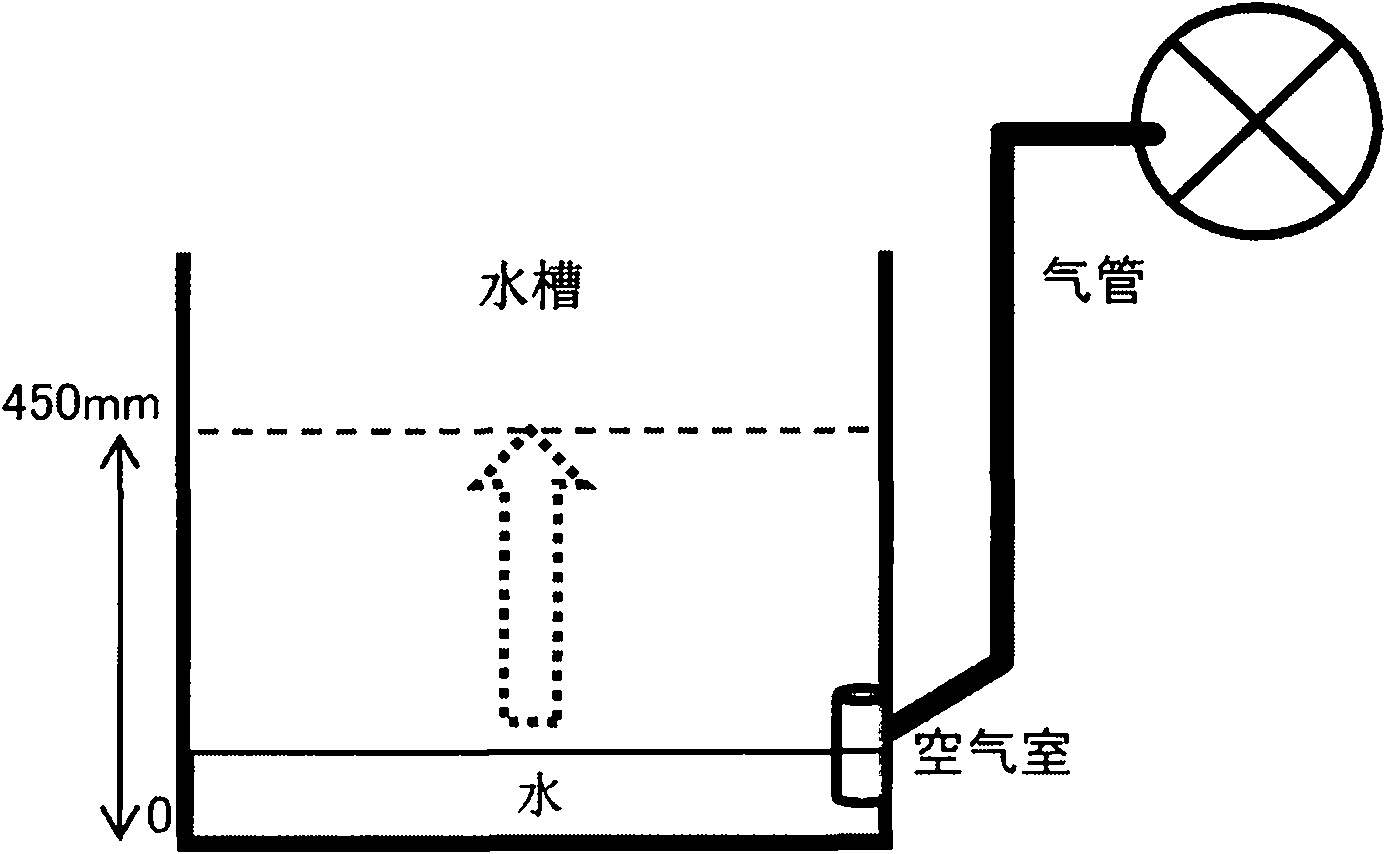
[0046] Let’s take the washing machine as an example, such as figure 2 As shown, the water tank inside the washing machine is provided with an air chamber communicating with the inside of the water tank. The air chamber is set at the bottom of the water tank. As the water level in the water tank rises, the water in the water tank will gradually enter and flood the air chamber. The chamber is connected to the pressure sensor through the air pipe, so as to detect the air pressure in the air chamber and obtain the information of the water level in the sink; in this embodiment, the initial position of the frequency signal curve of the pressure sensor is the zero of the water level in the sink Water level position, at this time the water in the sink does not enter the air chamber.

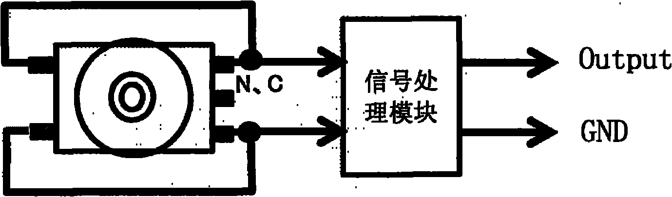
[0047] Such as image 3 As shown, the signal output terminal of the pressure sensor processes the frequency signal detected by the pressure sensor through the signal processing module, and transmits it to t...


PUM


Abstract

The invention relates to a control method of equipment containing a pressure sensor. The method comprises the following steps of: firstly, obtaining a frequency value of an initial position of a frequency signal curve of the pressure sensor and recording the frequency value in a control part of the equipment; secondly, comparing the frequency value of the initial position of the frequency signal curve of the pressure sensor with a frequency value of an initial position of a standard frequency signal curve set in the control part of the equipment to obtain a difference thereof; and thirdly, adding the difference after the control part of the equipment receives the frequency signal of the pressure sensor to obtain a corresponding frequency value of a standard frequency curve, wherein a value corresponding to the frequency value is a control value located by the pressure sensor. The frequency signal curve of the pressure sensor and the standard frequency signal curve in the control part of the equipment are corrected by obtaining the difference between the frequency signals of the initial position of the frequency signal curve of the pressure sensor and the frequency signals of the initial position of the standard frequency signal curve in the control part of the equipment without artificial regulation.

Description

Technical field [0001] The present invention relates to a control method of equipment, in particular to a control method for equipment containing pressure sensors. Background technique [0002] Pressure sensor is the most commonly used sensor in industrial practice. It is widely used in various industrial automation environments, involving water conservancy and hydropower, railway transportation, intelligent buildings, production automation, aerospace, military, petrochemical, oil well, electricity, ships, machine tools In many industries, such as, pipelines, the commonly used pressure sensors are as follows: [0003] 1. Strain gauge pressure sensor [0004] There are many types of strain gauge pressure sensors, such as resistance strain gauge pressure sensors, semiconductor strain gauge pressure sensors, piezoresistive pressure sensors, inductive pressure sensors, capacitive pressure sensors, resonant pressure sensors and capacitive acceleration sensors. But the most widely used i...

Claims


Application Information

Patent Timeline
Patent Type & Authority Applications(China)
IPC IPC(8): G05B19/04G05D15/01
Inventor 楼绍国
Owner 鸣志精密制造(太仓)有限公司
Why Eureka
Try Eureka