Reference clock source switching method and device
A technology of reference clock and clock source, applied in the field of wireless communication, can solve the problems of soft handover failure of communication system, avoid abnormal events of system clock, ensure the quality of system communication, and improve reliability.
- Summary
- Abstract
- Description
- Claims
- Application Information
AI Technical Summary
Problems solved by technology
Method used
Image
Examples
Embodiment 1
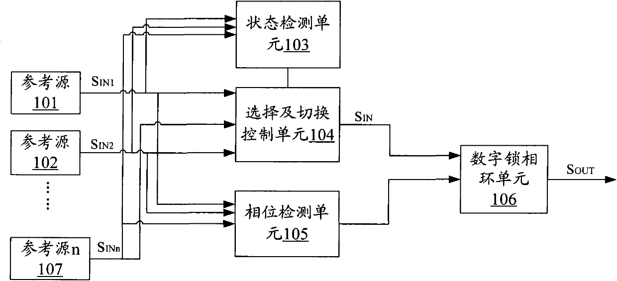
[0019] figure 1 It is a schematic structural diagram of a reference clock source switching device according to the first embodiment of the present invention. The device may be located in a synchronization processing device for synchronizing clock output signals in a digital communication device.
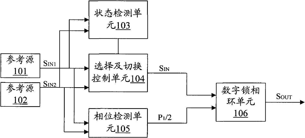
[0020] Such as figure 1 As shown, in the synchronization processing device for synchronizing clock output signals in digital communication equipment, multiple reference clock source inputs are received, namely figure 1 S shown by reference source 101 output IN1 , Reference source 102 output S IN2 Until the reference source S output by the reference source 107 INn (n is greater than 2). The device includes: a state detection unit 103 for real-time detection of the state of each reference clock source among multiple reference clock sources, and input the result to the selection and switching control unit 104; the selection and switching control unit 104 is connected to the state detectio...
Embodiment 2
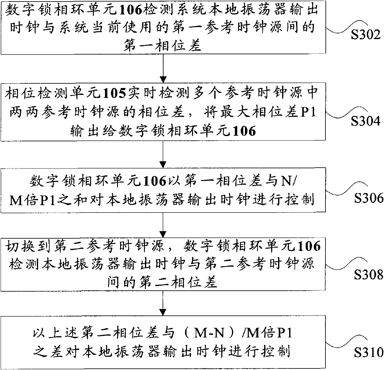
[0032] image 3 It is a flowchart of a method for switching a reference clock source according to the second embodiment of the present invention. figure 1 or figure 2 The device shown is implemented. The method mainly includes the following steps (step S302-step S310):
[0033] Step S302, the digital phase-locked loop unit 106 detects the first phase difference between the output clock of the system local oscillator and the first reference clock source currently used by the system;
[0034] For example, the state detection unit 103 detects the state of multiple reference clock sources of the system in real time, and outputs the detection results to the selection and switching control unit 104, and the selection and switching control unit 104 selects the first normal state according to the state of each reference clock source. The reference clock source is used as the currently used reference clock source, and the reference clock source is input to the digital phase-locked loop uni...
Embodiment 3
[0044] This embodiment is based on Figure 4 Each clock shown is taken as an example for description. In this embodiment, the reference clock sources of the system are reference source 1 and reference source 2, and M=2, N=1.
[0045] Figure 5 The flowchart for switching the reference clock source in this embodiment mainly includes the following steps:
[0046] Step S501: In the system startup phase, reference source 1, reference source 2, ..., reference source n (n=2 in this embodiment) are all initialized normally and the startup is completed;
[0047] Step S502: During the system warm-up phase, the system detects the status of each reference clock source in real time, and if the reference source status is normal, execute step S503 and step S506;
[0048] Step S503, detecting the phase difference between the two reference clock sources;
[0049] Step S504: Divide the value of the detected phase difference by 2 and save, that is, save the phase value P1 / 2;
[0050] Step S505, input P1 / 2...
PUM
 Abstract
Description
Claims
Application Information
 - R&D
- Intellectual Property
- Life Sciences
- Materials
- Tech Scout
- Unparalleled Data Quality
- Higher Quality Content
- 60% Fewer Hallucinations
Browse by: Latest US Patents, China's latest patents, Technical Efficacy Thesaurus, Application Domain, Technology Topic, Popular Technical Reports.
© 2025 PatSnap. All rights reserved.Legal|Privacy policy|Modern Slavery Act Transparency Statement|Sitemap|About US| Contact US: help@patsnap.com


