
Clock synchronization device and synchronization method thereof

A clock synchronization and clock signal technology, applied in synchronization devices, digital transmission systems, electrical components, etc., can solve the problems of communication system soft switching failure, hardware unit reset, one or more abnormal output clocks, etc., to avoid system clocks Abnormal events, improve reliability, and ensure the effect of system communication quality

Inactive Publication Date: 2010-06-16
ZTE CORP
View PDF3 Cites 0 Cited by
  • Summary
  • Abstract
  • Description
  • Claims
  • Application Information

AI Technical Summary

Problems solved by technology

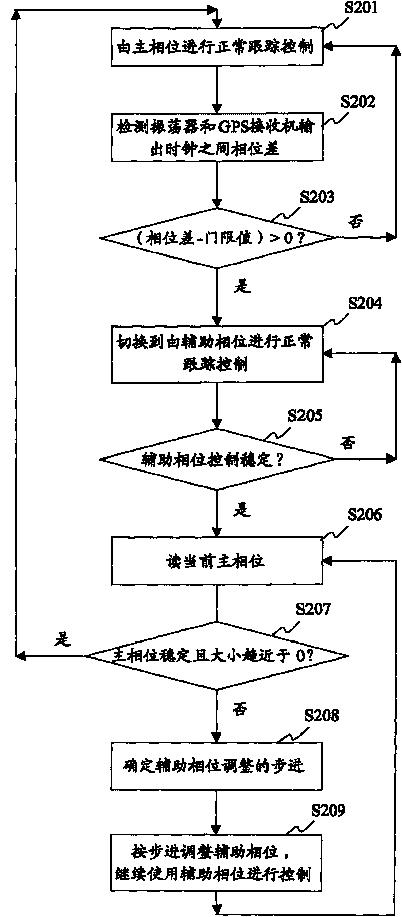
If the existing synchronization processing method is used, the output clock of the reference clock unit will be abnormal once or more during the process of synchronous tracking, and even cause the hardware units of relevant nodes in the network to reset, resulting in the failure of soft switching of the communication system in a short time

Method used


Image

  • Clock synchronization device and synchronization method thereof
  • Clock synchronization device and synchronization method thereof
  • Clock synchronization device and synchronization method thereof

Examples


Embodiment Construction

[0036] The preferred embodiments of the technical solutions of the present invention will be further described in detail below in conjunction with the accompanying drawings.

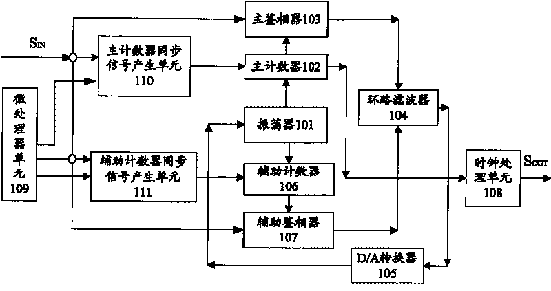
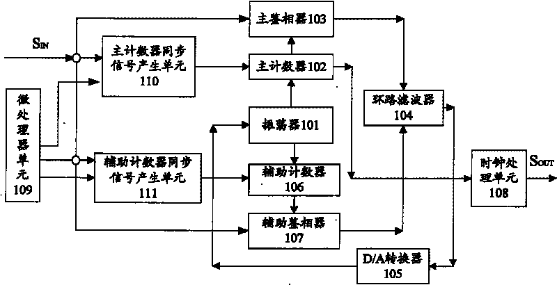
[0037] refer to figure 1 As shown, the synchronization processing device for synchronizing clock output signals in digital communication equipment uses the digital phase-locked loop on the reference clock unit to make the output clock signal of the oscillator 101 track the input reference clock signal S IN , so that the output clock signal S OUTSynchronized with the output clock signal of the oscillator 101, and finally the reference clock signal S IN , the clock signal output by the oscillator 101, the output clock signal S OUT The three are phase-synchronized. In the process of digital phase discrimination, the microprocessor unit 109 and the input reference clock S IN It works together with the main counter synchronization signal generation unit 110 or the auxiliary counter synchronization signal ...


PUM


Abstract

The invention discloses a clock synchronization device, comprising a main phase detector, a oscillator, a basic counter, a loop filter and a digital to analog converter (DAC). The invention adopts thetechnical proposal that: firstly, the clock signal sent out by the oscillator and the synchronous signal from outside are counted by the basic counter, and then transmitted to the main phase detector; secondly, the reference clock signal and the clock signal sent out by the oscillator is received by the main phase detector, and the phase difference between the two is detected, then a first phasedifference signal is generated and sent to the loop filter; thirdly, the first phase difference signal from the main phase detector is received and converted into voltage controlled bit by the loop filter, then transmitted to the digital to analog converter; finally, the digital signal is converted into analog signal by the digital to analog converter, and analog voltage is transmitted to the oscillator; wherein, the clock signal transmitted by the oscillator is regulated by the analog voltage. Meanwhile the utility model discloses a clock synchronization method.

Description

technical field [0001] The invention relates to a clock synchronization technology in wireless communication technology, in particular to a clock synchronization device and a synchronization method thereof. Background technique [0002] The wireless synchronization network is a physical network composed of node clock devices and timing links. Network synchronization refers to the distribution of timing signals to all nodes in the network in order to ensure the normal operation of the wireless communication network. The clock frequency and phase of all nodes in the network are strictly required. controlled within a certain tolerance range. [0003] In the wireless synchronization network, GPS (Global Positioning System) is used to configure the reference clock, and the reference clock unit tracks the PP1S (pulse of second) clock output by the GPS receiver. In the existing synchronization method, the clock output signal is adjusted to With the same frequency as the clock inpu...

Claims


Application Information

Patent Timeline
Patent Type & Authority Patents(China)
IPC IPC(8): H04L7/033H04B7/26
Inventor 王文静李宗安毕文仲向际鹰
Owner ZTE CORP
Learn More