Reference clock source switching method and device

A technology of reference clock and output clock, applied in the field of wireless communication, can solve the problems of soft handover failure of communication system, avoid abnormal events of system clock, ensure the quality of system communication, and improve reliability.

Active Publication Date: 2010-10-13
ZTE CORP
View PDF5 Cites 21 Cited by
  • Summary
  • Abstract
  • Description
  • Claims
  • Application Information

AI Technical Summary

Problems solved by technology

[0006] The main purpose of the present invention is to provide a reference clock source switching method and device, so as to at least solve the problem in the related art that the soft switching of the communication system fails due to the switching of the reference clock source

Method used


Image

  • Reference clock source switching method and device
  • Reference clock source switching method and device
  • Reference clock source switching method and device

Examples


Embodiment 1

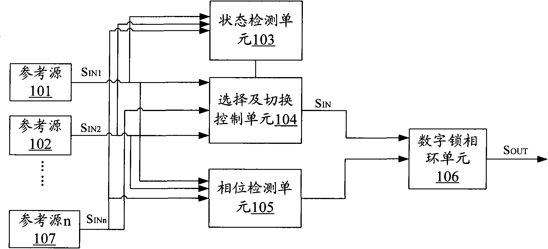
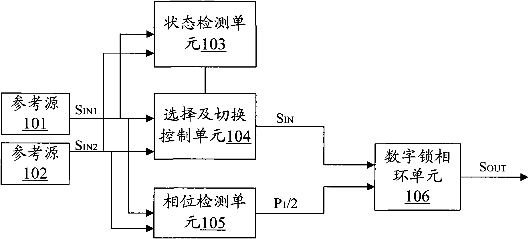
[0019] figure 1 It is a schematic structural diagram of a reference clock source switching device according to Embodiment 1 of the present invention, and the device may be located in a synchronization processing device for synchronizing clock output signals in a digital communication device.

[0020] Such as figure 1 As shown, in the synchronization processing device for synchronizing the clock output signal in the digital communication equipment, multiple reference clock source inputs are received, namely figure 1 The reference source 101 output shown in S IN1 , the reference source 102 output S IN2 , until the reference source 107 outputs the reference source S INn (n is greater than 2). The device includes: a state detection unit 103, which is used to detect the state of each reference clock source in multiple reference clock sources in real time, and input the result to the selection and switching control unit 104; the selection and switching control unit 104 is connec...

Embodiment 2

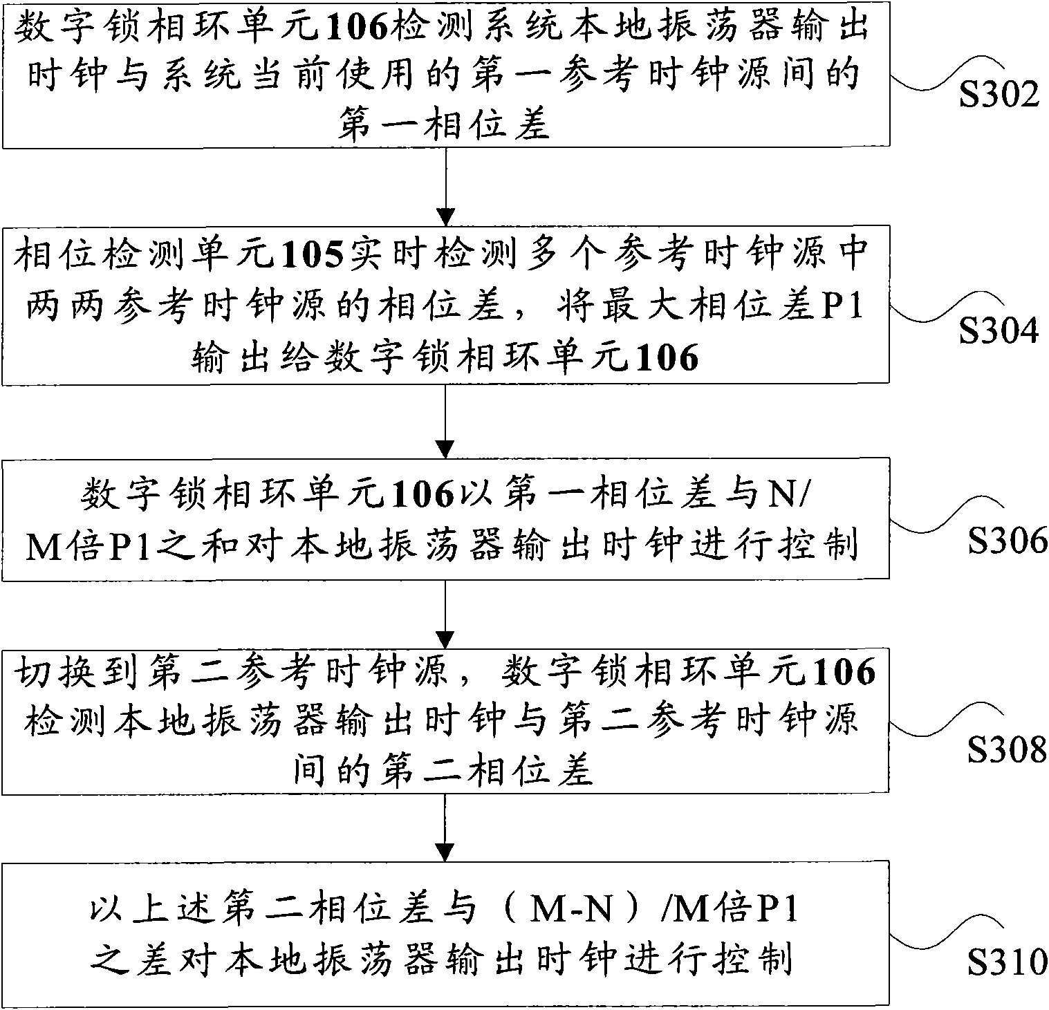
[0032] image 3 It is a flowchart of a reference clock source switching method according to Embodiment 2 of the present invention, the method can be implemented by figure 1 or figure 2 The device shown is implemented. The method mainly includes the following steps (step S302-step S310):

[0033] Step S302, the digital phase-locked loop unit 106 detects the first phase difference between the system local oscillator output clock and the first reference clock source currently used by the system;

[0034] For example, the state detection unit 103 detects the states of multiple reference clock sources of the system in real time, and outputs the detection result to the selection and switching control unit 104, and the selection and switching control unit 104 selects the first one in the normal state according to the states of each reference clock source. The reference clock source is used as the currently used reference clock source, and the reference clock source is input to th...

Embodiment 3

[0044] This embodiment takes Figure 4 Each clock shown is taken as an example for illustration. In this embodiment, the reference clock sources of the system are reference source 1 and reference source 2, and M=2, N=1.

[0045] Figure 5 It is a flow chart of switching the reference clock source in this embodiment, which mainly includes the following steps:

[0046] Step S501, in the system start-up phase, reference source 1, reference source 2, .

[0047] Step S502, in the system warm-up stage, the system detects the status of each reference clock source in real time, if the status of the reference source is normal, then execute step S503 and step S506;

[0048] Step S503, detecting the phase difference between two reference clock sources;

[0049] Step S504, divide the value of the detected phase difference by 2 and save, that is, save the phase value P1 / 2;

[0050] Step S505, inputting P1 / 2 as a phase difference input factor into the digital phase-locked loop unit 106;...


PUM


Abstract

The invention discloses reference clock source switching method and device, wherein the reference clock source switching method comprises the following steps of: detecting a first phase difference between a local oscillator output clock of a system and a first reference clock source currently used by the system; acquiring the maximal phase difference between pairwise reference clock sources of a plurality of reference clock sources of the currently detected system; controlling the local oscillator output clock through the sum of the first phase difference and N / M times of the maximal phase difference; detecting a second phase difference between the local oscillator output clock and a second reference clock source when the system is switched to the second reference clock source; and controlling the local oscillator output clock through the difference of the second phase difference and (M-N) / M times of the maximal phase difference, wherein the plurality of reference clock sources include the first reference clock source and the second reference clock source, M and N are natural numbers, and M is larger than N. The invention can be used for effectively preventing anomalous events of the system clocks from happening after switching.

Description

technical field [0001] The invention relates to the field of wireless communication, in particular to a reference clock source switching method and device in a base station system. Background technique [0002] In the existing wireless communication system, the base station needs an external clock source as a reference, and uses it to correct the local clock frequency. In the system, the clock source used to correct the local clock is called the reference clock source. [0003] At present, most of the wireless synchronization networks use the Global Positioning System (Global Position System, referred to as GPS) as the reference clock source to correct the reference clock; The output clock of the oscillator is tracked and controlled until the output clock of the oscillator is synchronized with the PP1S clock output by the GPS receiver, so that the clocks of other nodes in the system are synchronized with the reference master clock. [0004] Under certain application condit...

Claims


Application Information

Patent Timeline
Patent Type & Authority Applications(China)
IPC IPC(8): H03L7/099
Inventor 王文静
Owner ZTE CORP
Why Eureka
Try Eureka