
Process for the mould closure of an injection moulding machine, and mould closure

A closure device, injection molding machine technology, applied in the field of mold closure devices, can solve problems such as cracking of supporting elements

Inactive Publication Date: 2010-10-13
NETABTAL MASCHEN
View PDF4 Cites 3 Cited by
  • Summary
  • Abstract
  • Description
  • Claims
  • Application Information

AI Technical Summary

Problems solved by technology

It turned out to be unfavorable, or rather so unfavorable, that the solid support elements were already broken during prototype operation due to internal vertical support forces (Spreizkraft)

Method used


Image

  • Process for the mould closure of an injection moulding machine, and mould closure
  • Process for the mould closure of an injection moulding machine, and mould closure
  • Process for the mould closure of an injection moulding machine, and mould closure

Examples


Embodiment Construction

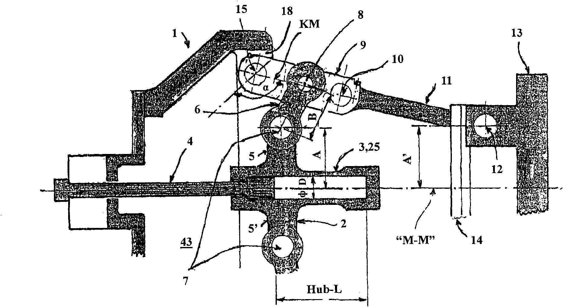
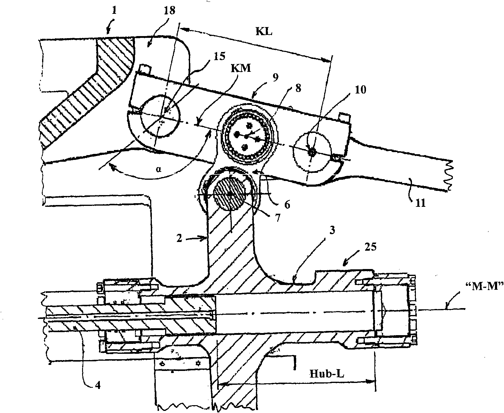
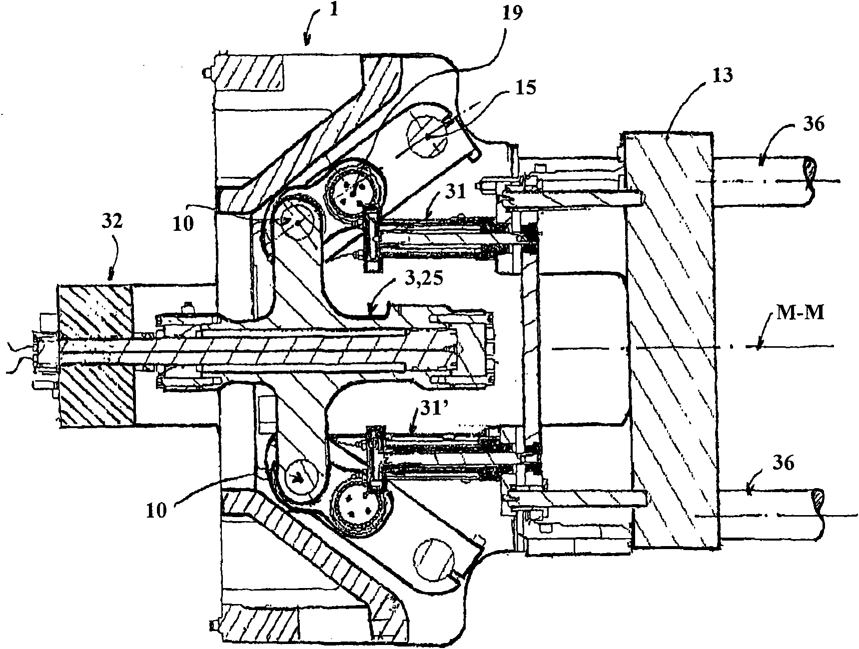
[0050] Refer below figure 1 . figure 1 Schematically shows the main elements on the side of the mold closing device with a 5-point toggle. On the left side of the figure is the support element 1, at which the support element 1 is hinged for the mold height adjustment member 26 ( Figure 7 ) drivers and crosshead drivers. Integrated in the crosshead 2 is a hydraulic cylinder 3 or a hydraulic drive 25 , the piston rod 4 of which is articulated on the outside of the bearing element 1 . The crosshead 2 has two vertically arranged projections 5, 5' on which a support plate 6 is mounted via an inner support plate bearing 7. The support plate engages at the toggle lever 9 via the support plate bearing 8 on the outside. On the left, the toggle lever 9 is articulated via a bearing hinge axis 15 at an articulation 18 of the bearing element 1 . On the opposite side, the toggle lever 9 is connected via a toggle hinge 10 to a mold moving lever 11 . On the right side of the drawing, t...


PUM


Abstract

The invention relates to a process for the mould closure of an injection moulding machine comprising a supporting element (1), a moveable tool clamping plate (13), 5-point toggle levers and a hydraulic drive (25) for the crosshead (2), and also to a mould closure. The crosshead drive is arranged between the supporting element (1) and the moveable tool clamping plate (13). The individual 5-point toggle levers are each embodied with a toggle lever (9), a mould movement lever (11, 11') and an expanding bracket (6). The movements for the mould closure are transmitted to the toggle levers (9) via expanding brackets (6). The expanding brackets (6) act in a central region of the toggle levers (9). The toggle levers (9) are embodied as articulated forks (20, 21), wherein the expanding brackets (6) act in a transverse web (22) of the articulated forks. The principal reaction forces of the mould forces are transmitted symmetrically to the supporting element (1) without lateral forces. The solution makes it possible to achieve a maximum pivot angle for the toggle levers (9), to use long toggle levers (9) and to achieve a maximum opening stroke for the mould halves.

Description

technical field [0001] The invention relates to a method for mold closing (Formschliessen) of an injection molding machine (Spritzgiessmachine) with a support element, a movable tool clamping plate (Werkzeugaufspannplatte), a 5-point toggle (5-Punkt-Kniehebel) And a hydraulic drive of the crosshead, wherein the crosshead drive is arranged between the support element and the movable tool clamping plate, and the movement of the mold closing is transmitted via the support plate to the toggle lever. [0002] The invention also relates to a mold closing device for an injection molding machine having a support element and a movable tool clamping plate and a hydraulic toggle drive with a crosshead arranged between the support element and the tool clamping plate , which respectively utilize the toggle lever, the mold moving lever and the support plate to form a 5-point toggle. Background technique [0003] Besides the injection equipment and the mold or tool, the mold closing devic...

Claims


Application Information

Patent Timeline
Patent Type & Authority Applications(China)
IPC IPC(8): B29C45/68
CPCB29C45/681
Inventor R·维恩曼P·温津M·斯普雷彻尔
Owner NETABTAL MASCHEN
Learn More