Machine tool dragging plate slide structure
A technology of sliding structure and carriage, which is applied in the direction of metal processing machinery parts, large fixed members, metal processing equipment, etc. It can solve the problems affecting the shape accuracy, position accuracy, dimension accuracy and surface roughness of the workpiece, and the workpiece cannot meet the use requirements, etc. question
- Summary
- Abstract
- Description
- Claims
- Application Information
AI Technical Summary
Problems solved by technology
Method used
Image
Examples
no. 1 approach
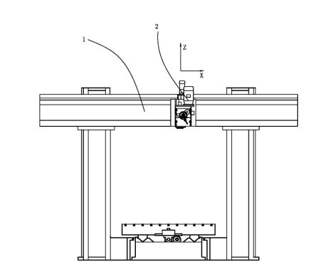
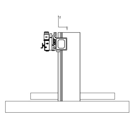
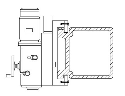
[0022] Such as figure 1 , figure 2 , Figure 4 and Figure 5 The sliding structure of the machine tool pallet shown includes a beam 1 and a pallet 2; the beam 1 is provided with a guide rail 3, and the pallet 2 is provided with two guide grooves 4 that can slide along the guide rail 3; The main shaft head 5 is installed; the top 20 of the guide groove 4 has a slope 6 downward, and the top 20 grooves of the two guide grooves 4 face the same direction; the guide rail 3 is a plane 30 corresponding to the top 20 of the guide groove 4 .
[0023] Such as Figure 4 and Figure 6 As shown, a guide slide 15 is installed on the top of the carriage 2, and the guide slide groove 4 positioned at the top of the carriage 2 is composed of the slope 6 and a side 151 of the guide slide 15, and the side 151 of the guide slide 15 is in contact with the vertical surface. The size of the included angle is-15-30 °, in the present embodiment, the included angle is 0 °; An included angle of 0°...
no. 2 approach
[0028] Such as figure 1 , figure 2 , Figure 7 The sliding structure of the machine tool pallet shown includes a beam 1 and a pallet 2; the beam 1 is provided with a guide rail 3, and the pallet 2 is provided with two guide grooves 4 that can slide along the guide rail 3; The main shaft head 5 is installed; the top 20 of the guide groove 4 has a slope 6 downward, and the top 20 grooves of the two guide grooves 4 face the same direction; the guide rail 3 is a plane 30 corresponding to the top 20 of the guide groove 4 . Such as Figure 7 As shown, an inclined surface 12 is also provided on the carriage. When the carriage 2 tends to tilt due to gravity, the inclined surface 12 has a restrictive effect on the carriage 2. In this way, the carriage 2 can be better prevented from detaching from the guide rail 3. .
[0029] A fixed plate 7 is fixedly installed on the lower surface of the carriage 2, and one end of the fixed plate 7 breaks away from the abutment 71 of the guide r...
no. 3 approach
[0033] Such as figure 1 , figure 2 and Figure 8 The sliding structure of the machine tool pallet shown includes a beam 1 and a pallet 2; the beam 1 is provided with a guide rail 3, and the pallet 2 is provided with two guide grooves 4 that can slide along the guide rail 3; The main shaft head 5 is installed; the top 20 of the guide chute 4 has a slope 6 and another second slope 13 downwards, and the angle between the second slope 13 and the vertical plane is 30-90°. In this embodiment , the included angle is 45°, and the tops 20 of the two guide grooves 4 face the same direction; the guide rail 3 corresponds to a plane 30 at the top 20 of the guide grooves 4 .
[0034] A fixed plate 7 is fixedly installed on the lower surface of the carriage 2, and one end of the fixed plate 7 breaks away from the abutment 71 of the guide rail 3 for preventing the carriage from jumping upwards, which improves the safety of the machine tool.
[0035]During the processing of the machine to...
PUM
 Abstract
Description
Claims
Application Information
 - R&D Engineer
- R&D Manager
- IP Professional
- Industry Leading Data Capabilities
- Powerful AI technology
- Patent DNA Extraction
Browse by: Latest US Patents, China's latest patents, Technical Efficacy Thesaurus, Application Domain, Technology Topic, Popular Technical Reports.
© 2024 PatSnap. All rights reserved.Legal|Privacy policy|Modern Slavery Act Transparency Statement|Sitemap|About US| Contact US: help@patsnap.com


