Work clamp of stator pressing plate

A tooling fixture and pressure plate technology, applied in the field of tooling fixtures, can solve the problem of low assembly accuracy and achieve the effect of improving labor productivity

Inactive Publication Date: 2010-10-20
YICHANG JIANGXIA MARINE MACHINERY
View PDF0 Cites 14 Cited by
  • Summary
  • Abstract
  • Description
  • Claims
  • Application Information

AI Technical Summary

Problems solved by technology

[0003] The technical problem to be solved by the present invention is to provide a fixture for st...

Method used


Image

  • Work clamp of stator pressing plate
  • Work clamp of stator pressing plate
  • Work clamp of stator pressing plate

Examples


Embodiment Construction

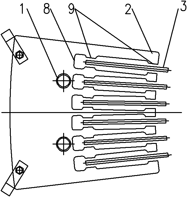
[0018] Such as figure 1 , figure 2 Among them, a tooling fixture for a stator pressure plate, the clamp body 2 is provided with two C-shaped clamps at one end, two positioning pins 1 at the middle, and a plurality of opening slots arranged in an arc at the other end, and positioning pins are provided in the opening slots. Partition 3. The bottom end of the open slot is provided with a positioning arc line 8, and the two sides of the open slot are provided with four positioning constrictions 9, two respectively at the two sides of the open slot.

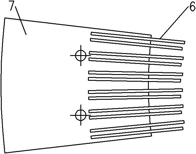
[0019] A row of deep opening slots are milled on the clamp body 2 by machining. The opening slots are processed into a certain angle according to the product requirements. On the arc, the relative position of the rack 6 is positioned by using two spaced positioning necks 9 and the positioning partition 3 in the groove. The thickness of the positioning partition 3 is processed according to the thickness of the rack 6 and the groove...


PUM


Abstract

The invention discloses a work clamp of a stator pressing plate, wherein one end of a clamp body is provided with a C-shaped clamp, the middle part of the clamp body is provided with at least one positioning pin, the other end of the clamp body is provided with a plurality of opening grooves which are arranged in a circular arc, and a positioning separator is arranged in each opening groove; and the bottom of each opening groove is provided with a positioning circular arc line, and two sides of each opening groove are provided with a plurality of positioning reduced necks. The invention can ensure that the assembly between racks and the pressing plate and the after-welding precision reach the requirement of a blueprint, even if all rack end parts are positioned in the same positioning circular arc, and the size error is +/-0.5 mm, and the deviation of rack angles is controlled to be within +/-0.05 degrees. In the invention, the stator pressing plate is welded so that the labor production ratio is at least increased by over one time.

Description

technical field [0001] The invention relates to a tooling fixture, in particular to a tooling fixture for a hydraulic generator stator pressure plate. Background technique [0002] The stator is an important part of the hydroelectric generator system. The stator pressing plate is mainly used to compress the generator stator, and the rack on it is embedded in the stator coil to fix it. According to the size of the generator stator, the stator pressure plate and the rack can be directly processed from the whole blank or welded from two separate parts. When using a welded structure, from image 3 and Figure 4 It can be seen that the assembly and welding tolerance requirements between the rack and the pressure plate are relatively high. Usually, the method of scribing lines on the template is used for assembly, and the error is relatively large. It often occurs that the ends of each rack are not on the same positioning arc line, and the accuracy of the assembly angle of the r...

Claims


Application Information

Patent Timeline
IPC IPC(8): B23K37/04
Inventor 罗中喜
Owner YICHANG JIANGXIA MARINE MACHINERY
Why Eureka
Try Eureka