
Hard alloy blade for improving cutting edge structure

A cemented carbide insert and cutting edge technology, which is applied to tools for lathes, accessories of toolholders, metal processing equipment, etc. To avoid problems such as poor wear resistance of the surface, it can achieve the effect of avoiding knife burning, improving edge strength and avoiding wear.

Active Publication Date: 2012-09-26
ZHUZHOU CEMENTED CARBIDE CUTTING TOOLS CO LTD
View PDF9 Cites 0 Cited by
  • Summary
  • Abstract
  • Description
  • Claims
  • Application Information

AI Technical Summary

Problems solved by technology

However, in the subsequent application practice, we found that the existence of the enriched binder phase surface area reduces the yield strength and hardness of the blade material, resulting in plastic deformation of the cutting edge of the blade and a decrease in the wear resistance of the flank
CN101214743A Chinese patent document discloses a coated blade for processing cast iron. The two sides of the cutting edge of the blade matrix form a bonding phase-enriched surface area, and the fan-shaped area in the middle of the bonding phase-enriched surface area is cubic phase-enriched. The structure improves the plastic deformation resistance of the cutting edge, but in high-speed and high-efficiency cutting of steel and stainless steel, the flank wear resistance performance is poor, and the plastic deformation resistance needs to be further improved.

Method used


Image

  • Hard alloy blade for improving cutting edge structure
  • Hard alloy blade for improving cutting edge structure
  • Hard alloy blade for improving cutting edge structure

Examples


Embodiment 1

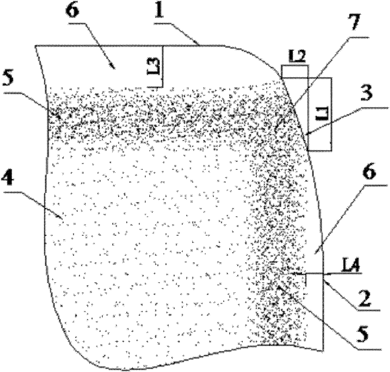
[0019] a kind of like figure 1 The cemented carbide insert with improved cutting edge structure shown includes a cutting edge 3 formed by the intersection of the rake face 1 and the flank face 2. All alloys present a gradient change structure, the gradient change structure refers to the transition from the homogeneous alloy zone 4 of the inner layer to the cubic carbonitride enriched zone 5, and then to the binder phase enriched surface zone 6, the cutting edge The intersection region 7 of the gradient structure on both sides of 3 at the cutting edge 3 is a cubic carbonitride enriched region 5, and the junction region 7 basically does not contain the binder phase enriched surface region 6, which is exposed on the surface of the cutting edge 3 The length L1 of the cubic carbonitride-rich surface region in the direction perpendicular to the rake face 1 is about 40 μm, and the cubic carbonitride-rich surface region exposed on the surface of the cutting edge 3 is in the direction ...

Embodiment 2

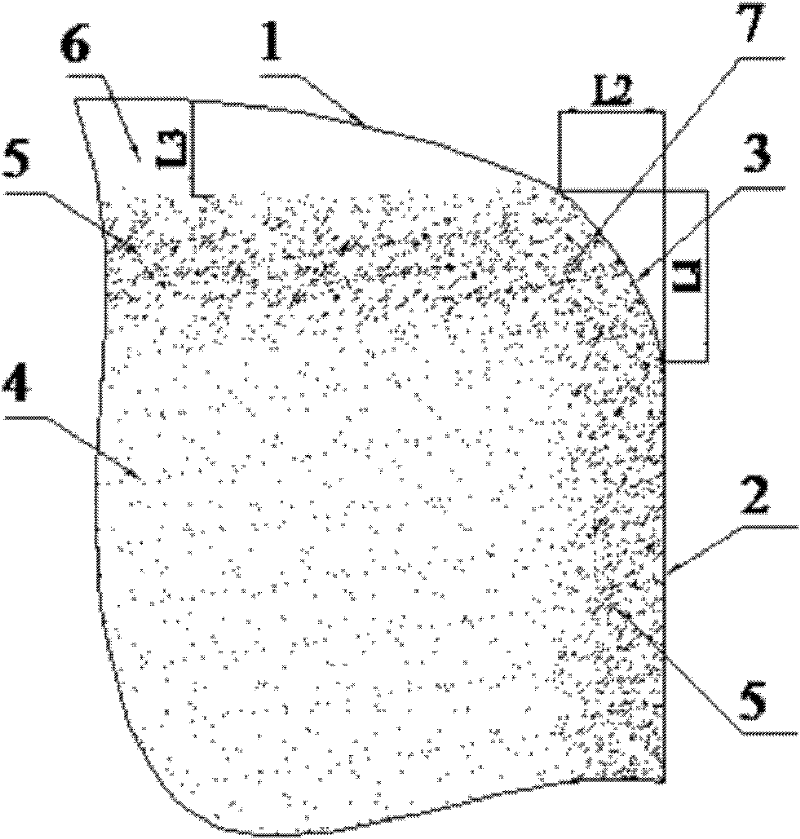
[0028] a kind of like figure 2 The cemented carbide insert with improved cutting edge structure shown includes a cutting edge 3 formed by the intersection of the rake face 1 and the flank face 2. All alloys present a gradient change structure, the gradient change structure refers to the transition from the homogeneous alloy zone 4 of the inner layer to the cubic carbonitride enriched zone 5, and then to the binder phase enriched surface zone 6, the cutting edge The intersection region 7 of the gradient structure on both sides of 3 at the cutting edge 3 is a cubic carbonitride enriched region 5, and the junction region 7 basically does not contain the binder phase enriched surface region 6, which is exposed on the surface of the cutting edge 3 The length L1 of the cubic carbonitride-rich surface region in the direction perpendicular to the rake face 1 is about 40 μm, and the cubic carbonitride-rich surface region exposed on the surface of the cutting edge 3 is in the direction...

Embodiment 3

[0031] On the basis of the cemented carbide insert with improved cutting edge structure obtained in the above-mentioned embodiment 2, the coating method is carried out according to the coating method described in embodiment 1, and the cemented carbide coating with improved cutting edge structure of the present embodiment is obtained. Layer blades.


PUM

PropertyMeasurementUnit
thicknessaaaaaaaaaa
thicknessaaaaaaaaaa
crystal sizeaaaaaaaaaa

Abstract

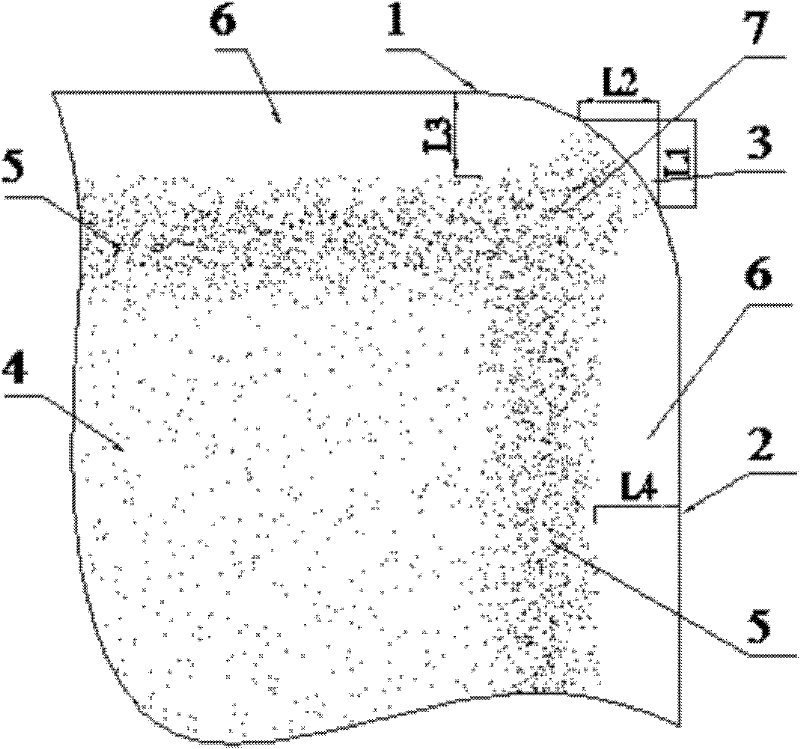
The invention discloses a hard alloy blade for improving a cutting edge structure, comprising at least one cutting edge formed by crossing a front knife face and a rear knife face. Hard alloys of the front knife face and the rear knife face at both sides of the cutting edge are in a gradient change structure, i.e. the transition from a homogeneous alloy region on an inner layer to a cubic carbon and nitrogen compound enrichment region and then to a binder-phase enrichment surface region, the gradient change structure mainly refers to the cubic carbon and nitrogen compound enrichment region ina confluence region at the cutting edge, and the length L1 of a cubic carbon and nitrogen compound enrichment surface region exposed at the cutting edge, which is perpendicular to the length of the front knife face, is greater than a length L2 perpendicular to the rear knife face. The hard alloy blade for improving the cutting edge structure has the advantages of high toughness, wear resistance, long service life, and the like.

Description

technical field [0001] The invention relates to a cemented carbide blade, in particular to a cemented carbide blade with improved local structure. Background technique [0002] During the machining of carbide-coated inserts, there are two failure regimes: wear and breakage. Blade wear mainly includes abrasive wear, adhesive wear, diffusion wear and oxidation wear. Under different cutting conditions, when processing workpieces of different materials, the main cause of wear may be one or two of them. Generally speaking, when the cutting temperature is low, it is mainly abrasive wear, and when the cutting temperature is high, it is mainly diffusion wear and oxidative wear. Blade damage is mainly brittle damage (chipping, chipping, peeling, crack damage, etc.) and plastic deformation. The experimental data show that the early damage of the blade is mainly caused by brittle damage caused by mechanical impact; the later fatigue damage of the blade is mainly caused by the brittl...

Claims


Application Information

Patent Timeline
Patent Type & Authority Patents(China)
IPC IPC(8): C23C14/06C23C16/36B23B27/14
Inventor 刘王平陈响明王社权李秀萍王以任
Owner ZHUZHOU CEMENTED CARBIDE CUTTING TOOLS CO LTD
Learn More