
Water channel structure of cylinder cover

A cylinder head and water channel technology, applied in the directions of cylinder head, cylinder, engine components, etc., can solve the problem of uneven cooling in the four nose bridge areas, and achieve the effects of simple structure, reduced temperature stress, and uniform cooling

Inactive Publication Date: 2010-10-20
WUXI KIPOR POWER CO LTD
View PDF0 Cites 14 Cited by
  • Summary
  • Abstract
  • Description
  • Claims
  • Application Information

AI Technical Summary

Problems solved by technology

Usually, when the structure and strength permit, the cooling channel is drilled in the high temperature part, and the water flow direction can only flow from one direction to the injector, and the cooling of the four nose bridge areas is not very uniform.

Method used


Image

  • Water channel structure of cylinder cover
  • Water channel structure of cylinder cover
  • Water channel structure of cylinder cover

Examples


Embodiment Construction

[0014] The present invention will be further described below in conjunction with specific drawings and embodiments.

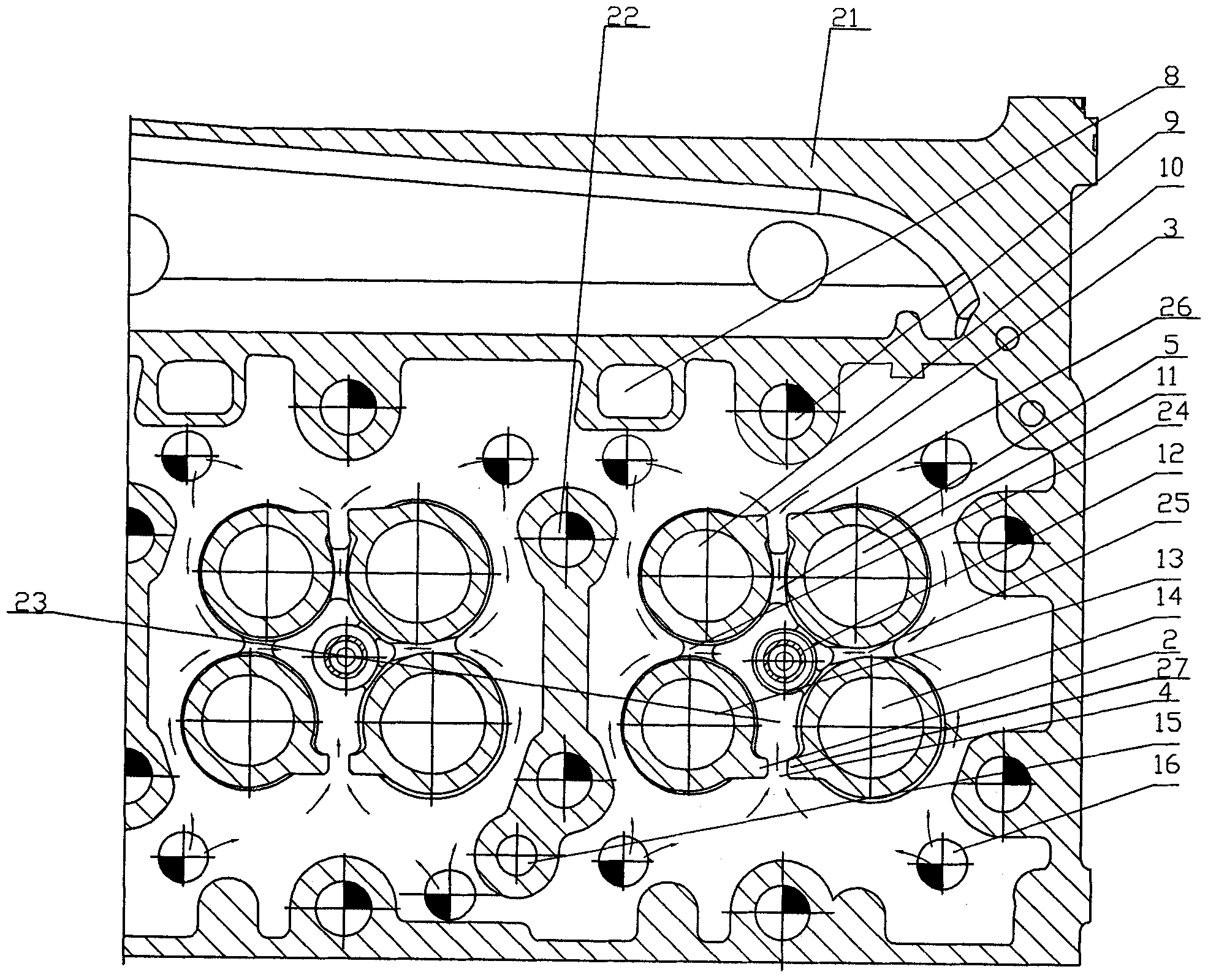
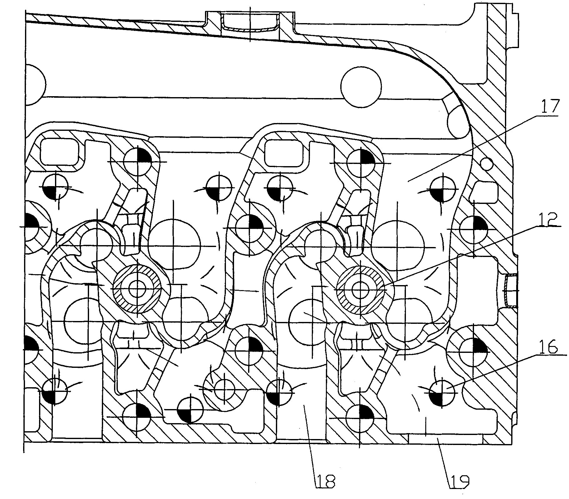
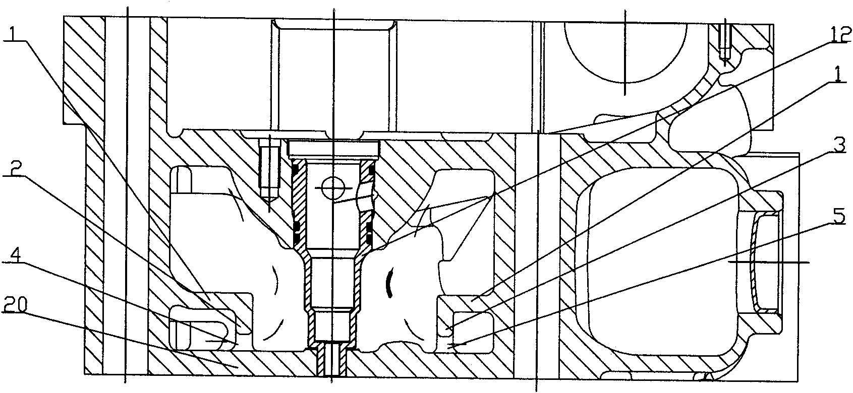
[0015] As shown in the figure: horizontal plate 1, third nose bridge convex plate 2, first nose bridge convex plate 3, second auxiliary waterway 4, first auxiliary waterway 5, lower waterway 6, upper waterway 7, respiratory tract 8, bolt holes 9, The first exhaust valve seat hole 10, the first intake valve seat hole 11, the injector bushing 12, the second exhaust valve seat hole 13, the second intake valve seat hole 14, the oil return hole 15, the water inlet Hole 16, air intake channel 17, exhaust channel 18, water outlet 19, cylinder head 21, oil inlet hole 22, communication channel 23, first communication hole 24, second communication hole 25, second nose bridge convex plate 26 and the first Four nose beam convex plates 27 and other parts constitute.

[0016] The cylinder head waterway structure includes the first intake valve seat hole 11, the first exhaus...


PUM


Abstract

The invention relates to a water channel structure of a cylinder cover, which comprises a first air inlet hole base, a second air inlet hole base, a first vent hole base, a second vent hole base and a fuel injector sleeve arranged on the cylinder cover. A bolt hole, an oil inlet hole and an oil return hole are formed on the cylinder cover; a lower layer water channel and an upper layer water channel are formed in the cylinder cover around a first inlet valve base hole, a first exhaust valve base hole, a second inlet valve base hole, a second exhaust valve base hole, an inlet channel and an exhaust channel; the lower layer water channel is communicated with the upper layer water channel through a communicating water channel; a first intercommunicating pore is formed between the first exhaust valve base hole and the second exhaust valve base hole to communicate the lower layer water channel on one side with the communicating water channel; and a second intercommunicating pore is formed between the first inlet valve base hole and the second inlet valve base hole to communicate the lower layer water channel on the other side with the communicating water channel. The water channel structure of the cylinder cover can reduce temperature stress of the cylinder cover to ensure that an inlet valve base, an exhaust valve base and the fuel injector sleeve are cooled uniformly, avoid capillary cracks and prolong the service lives of the inlet valve base, the exhaust valve base and the fuel injector sleeve.

Description

technical field [0001] The invention relates to the field of cylinder heads of internal combustion engines, in particular to a cylinder head provided with multi-layer water channels. Background technique [0002] In the cylinder head, the area between the intake and exhaust valve seats, between the exhaust valve seats, and between the valve seat and the injector is a high-temperature zone, which is located in the center of the cylinder. When the internal combustion engine is working, this area is subjected to high temperature and high pressure alternating loads. Due to the alternating stress generated by the load change, fine cracks begin to appear in this area after a certain period of time, and then gradually expand and finally crack. In order to reduce the temperature stress of the cylinder head, special cooling measures should be taken in the high temperature area. Usually, when the structure and strength permit, the cooling channel is drilled in the high temperature pa...

Claims


Application Information

Patent Timeline
Patent Type & Authority Applications(China)
IPC IPC(8): F02F1/42F02F1/40
CPCF02F1/42F02F1/40
Inventor 肖亨琳
Owner WUXI KIPOR POWER CO LTD
Learn More